Parameters of structural model
The parameters describing structural model are summarised in the table below.
|
priority definition |
This parameter specifies "how" the priority will be defined. |
|
The value defines the priority of the 1D member. |
|
|
perpendicular alignment |
This option specifies the alignment of the 1D member to its middle axis. |
|
This parameter defines eccentricity that may be introduced. |
|
|
eccentricity ey, ez |
Depending on the previous parameter, the eccentricity can be specified. |
|
end cuts |
End-cuts can be defined automatically or manually. See below. |
|
offset parameters |
Offset parameters differ for automatic and manual end-cuts. See below. |
In addition, there is one more parameter related to structural model. The basic beam parameterType defines the structural type of 1D member. This parameter defines the priority of the 1D member if the priority is specified according to member.
Priority
The priority is taken into account when connection of intersecting or touching 1D members is solved. The meaning will be best explained on a small example.
Let’s assume a column with a 1D member attached to its head. The calculation model looks like:
Now, let’s display the structural model. The priority of the column (B17) is set to 100. The priority of the inclined 1D member (B18) is set to 80. The automatically created detail will look like:
Now, let’s decrease the priority of the column (B17) to 50. The result will be:
Perpendicular alignment
If adjusted to default value, the alignment of the structural model is taken from the alignment of the calculation model.
Eccentricity
The eccentricity may be defined in several ways:
|
whole member |
The eccentricity is constant along the 1D member. |
|
each end point |
The eccentricity is defined separately for the two end points. In between, it varies linearly. |
|
purlin on rafter |
The eccentricity is so adjusted so that one member is put (laid) on the other. This option is useful mainly for "intersecting" 1D members that touch with their surfaces. See below. |
Purlin on rafter
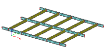
The effect of this option is shown on the following two pictures. The first one shows intersecting beam without defined eccentricity.
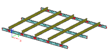
In the second picture, option Purlin on rafter is assigned to transverse beams. As a result they are put atop the other two beams.
Note 1: The priority of "purlins", i.e. the beams with Purlin on rafter option must be lower than the priority of the intersecting beams. Otherwise, the setting will have no effect.
Note 2: Purlins and rafters must be connected by means of linked nodes. Otherwise the automatic calculation of vertical offset cannot be performed.
End cuts
Automatic end cuts
Automatic end cuts are calculated automatically. Individual 1D members are so adjusted to make a neat detail in joints. In addition, it is possible to define a gap that must be made between the face of the given 1D member and the joined member.
|
x-gap begin |
gap at the beginning of the 1D member |
|
x-gap end |
gap at the end of the 1D member |
Manual end cuts
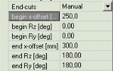
The user may define the detail of the 1D member end manually. This may be useful for large models that do not change any more. Once the manual end cut is adjusted, there is no need to calculate it again when the model is regenerated. It also enables the user to design special details.
|
begin x-offset |
end cut in longitudinal direction at the beginning of the 1D member |
|
begin Rz |
inclination Rz of the face of the 1D member at the beginning of the 1D member |
|
begin Ry |
inclination Ry of the face of the 1D member at the beginning of the 1D member |
|
end x-offset |
end cut in longitudinal direction at the end of the 1D member |
|
end Rz |
inclination Rz of the face of the 1D member at the end of the 1D member |
|
end Ry |
inclination Ry of the face of the 1D member at the end of the 1D member |
Example
|
beam: automatic end cut |
|
|
beam: automatic end cut gap = 50 mm |
|
|
beam: manual end cut |
Offset filled in from previous automatic end cut. The end offset is 50 mm bigger than the beginning offset. |
|
beam: end offset = 500 |
|
|
beam: end offset = 0 Ry = 135 column: Ry = 45 |


