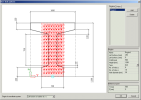
Defining a new bore hole pattern
Procedure to define a new bore hole pattern
-
Open the Bore hole pattern manager.
-
Click button [New].
-
Select the cross-section for which the new bore hole pattern should be defined.
-
Close the Cross-section database manager.
-
The editing dialogue for a bore hole pattern opens on the screen.
-
Define the bore hole pattern.
-
Confirm with [OK].
Editing dialogue for a bore hole pattern
The dialogue for the definition or editing of a bore hole pattern consists of the following parts:
-
graphical window,
-
definition of coordinate system,
-
section of the input of regions and holes,
-
definition of reference point.
Graphical window
The graphical window displays the selected cross-section and the defined pattern of holes. It supports standard features of SCIA Engineer graphical windows:
-
[Ctrl] + [Shift] + right-click and drag to zoom in and out the drawing,
-
[Shift] + right-click and drag to move the drawing.
Definition of coordinate system
You may select the origin of the input-coordinate-system. The selected system is marked in the graphical window. For example:
Input of regions and holes
The holes in the plate may be defined individually one-by-one or en-block in specified regions (even the region may contain just one hole).
Regions
A region is always rectangular and is defined by its position in the cross-section and its size. The holes are always regularly distributed across the region. You may specify either (i) the number of holes in the horizontal and vertical direction or (ii) the position of the first hole in each direction and the distance between the holes in that direction.
|
Name
|
Specifies the name of the region. |
|
Left bottom y Left bottom z |
Defines the coordinates of the bottom left the corner of region. |
|
Width
|
Specifies the width of the region. |
|
Height
|
Specifies the height of the region. |
|
Type
|
You may select the type of definition of the holes in the region: Grid – you define the number of the holes in each direction Increment - you define the position of the first hole in each direction and the distance between the holes in that direction |
|
No. of holes y No. of holes z |
Inputs the holes for type Grid. |
|
First hole y First hole z |
Inputs the holes for type Increment. Defines the position of the first hole. |
|
Dy Dz |
Inputs the holes for type Increment. Specifies the distance between individual holes. |
|
Hole diameter
|
Defines the hole diameter. |
Holes
Holes may be input directly by their position in the cross-section.
|
ID |
(informative) Shows the number of the hole. The number are assigned automatically by the program. |
|
Name
|
Specifies the name of the hole. |
|
Y Z |
The coordinates defining the position of the hole. |
|
Hole diameter
|
Defines the hole diameter. |
Holes can be copied. In that case you specify if you make just a single copy or a multiple copy, input the distance between the copies and, if required, also the number of copies. In order to copy a hole, simply use button [Copy] next to the list of holes and fill in the copy-dialogue.
Note: When you define the holes in regions, it may happen that some holes "fall" out of the cross-section (especially if the cross-section is not rectrangular). These outside holes do not have to be specially treated as they are automatically filtered when you define the sectional strand pattern. That means that strands can be put only into real and proper holes.
|
Defined holes in the bore hole pattern
|
|
|
Available holes in the sectional strand pattern |
Reference point
The reference point can be used to position the bore hole pattern in the cross-section of the 1D member when the sectional strand pattern is created (you are asked to position the bore hole pattern on the cross-section). Normally, you may accept the default setting. Only if you decide on a special configuration of the bore hole pattern, it may be convenient to "play" with the reference point and use one bore hole pattern for different final location of strands in the 1D member.


