Parameters of the post-tensioned internal tendon
General
Geometry
|
Geometry input |
Selects the type of the geometry input. Source geometry For this type of geometry, the user must define the shape of the tendon geometry in advance. The predefined tendon is then allocated to the 1D member and, if necessary, modified in its shape to follow the shape of the 1D member. The tendon is not stretched to fit the length of the 1D member. But, it may be curved to follow the real shape of the 1D member. The latter may be used to simplify the input of tendons in curved 1D members. The tendon is defined by its "projection" into plane. Then, it is allocated to the curved 1D member. The shape of the tendon is modified, so that the local x-axis of the tendon follows precisely the local x-axis of the 1D member. Direct input For this type of geometry input, the user defines directly the shape of the tendon in the graphical screen where the 1D member to-be-reinforced is displayed. In order to define exactly the shape that is required, an additional toolbar is added to the top of the command line. This added toolbar allows for the input of circular and parabolic intervals. Reference line with source geometry This possibility is a kind of combination of the two previous options. For more information read a separate paragraph at the end of this chapter.
Note: The same toolbar is displayed when e.g. a new 1D member is input. |
|
LCS |
Specifies the way in which the local coordinate system of the tendon (y- and z- axis) is defined. |
|
Source geometry |
(This item is available only if the Geometry input is set to Source geometry) Here, the user must select the required source geometry for the tendon. It is also possible to invoke the Tendon source geometry manager and input a new source geometry. |
|
Origin of source geometry |
(This item is available only if the Geometry input is set to Source geometry) It is necessary to define where the origin of the source geometry is to be put in the model. In other words, the user must position his/her tendon into the 3D space. The position is defined by (i) the offset from the origin of the coordinate the local coordinate system of the allocated 1D member or (ii) in the global coordinates. |
|
Coord.X, Y, Z |
(This item is available only if the Geometry input is set to Source geometry) These three values define the position of the tendon source geometry origin. The exact meaning depends on the adjustment made in the item above. |
Material
Picture: Tendon groups

Stressing
|
Type of stressing |
The type of stressing is analogous to pre-tensioned tendons. |
|
Prestressing from |
The program offers four options. Simultaneous anchoring of both ends is neither economic nor practically feasible. The options offered in the list are self-explanatory. |
|
Coefficient of friction in curved part of tendon |
Friction coefficient for curved part of tendon. |
|
Coefficient of friction in straight part of tendon |
(only for CSN / STN standard) Friction coefficient for the straight part of tendon. |
|
Unintentional angular displacement |
(only for EC2, NEN) The unintended angular displacement of the tendon. |
|
Anchorage set
|
Defines the anchorage set at the beginning of the tendon. |
|
Stress during correcting |
Defines the anchorage set at the end of the tendon. |
|
Duration of keeping stress |
Specifies the duration of keeping constant stress during the correction of relaxation. |
|
Initial stress – begin
|
Initial stress at the beginning of tendon (before seating). |
|
Defines the part of the tendon at its beginning which is taken into account when calculating the losses, but not when creating the structural model. This is useful in the case that the 1D member (and tendon) protrudes beyond the theoretical support and the user does not want to include this part of the structure into the model, but wants to have proper losses and tendon geometry for the export into CAD. |
|
|
Overhang of tendon not included in structural model – end |
Analogous to the previous item. |
|
Defines sections where results are presented. |
Arc
(These items are available only if the Geometry input is set to Direct input)
Picture: Circle + tangent; Cicle + radius

Picture: Symmetric parabola + tangent

Reference line with source geometry
The user-defined source geometry is winded on the user defined reference line. The reference line is a curve that defines x coordinates of the local coordinate system of the tendon. The source geometry is related to this curve. The centreline of the beam was the reference line for the tendons in version SCIA Engineer 2008. In version SCIA Engineer 2008.1 it is possible to select any user-defined curve as the reference line.
The following rules apply:
• IF the source geometry of the tendon is longer than the reference line, then the geometry of the tendon continues from the end of the reference line up to the length of the source geometry; the direction of the tendon from the end of the reference line is taken from the direction of the last point of the reference line
• IF the source geometry is shorter than the reference line, then the source geometry is winded on the reference line only up to the length of the source geometry.
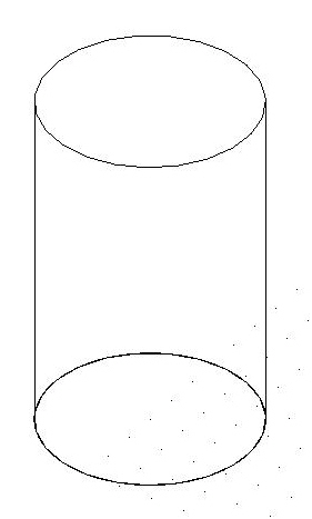
The example of the use of the new definition of the tendon geometry is a tendon of a spiral shape allocated on a cylindrical shell. The reference line is defined as the circle in the base of the cylinder. The source geometry is defined as a line in vertical and horizontal projection. The elevation of the spiral is provided by the elevation of the Source geometry in the vertical projection.
|
Structure |
|
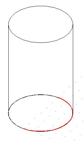
|
Reference Line |
|
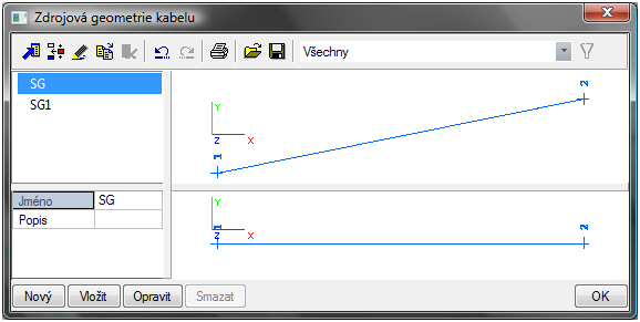
|
Tendon Source Geometry Dialogue |
|
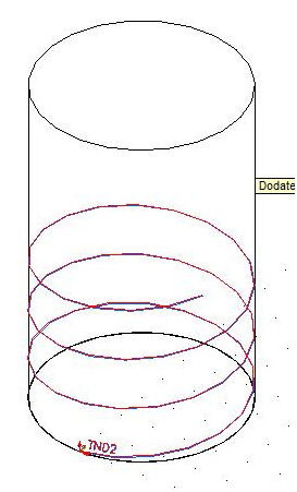
|
Final Geometry |
|