Calculated results for 2D members
Internal forces
Principal moments – plate
|
Label |
Description |
Calculation |
|
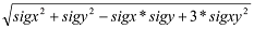
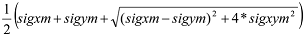
m1 |
Principal moment (max) |
|
|
m2 |
Principal moment (min) |
|
|
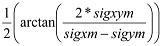
alfa (bending) |
Angle of principal moment m1 |
|
|
mtmax |
Maximum torque moment |
|
|
qmax (bending) |
Maximum shear force perpendicular to the plane |
|
|
beta |
Angle of maximum shear force |
|


Principal forces – wall
|
Label |
Description |
Calculation |
|
n1 |
Principal force (max) |
|
|
n2 |
Principal force (min) |
|
|
Angle of principal force n1 |
|
|
|
qmax (membrane) |
Maximum shear force in the plane |
|


Design moments from EC2 – plate
|
Label |
Description |
Calculation |
|
mxD+ |
Design moment in x-direction on positive surface
|
|
|
myD+ |
Design moment in y-direction on positive surface |
|
|
mcD+ |
Design moment in the concrete on positive surface |
|
|
mxD- |
Design moment in x-direction on negative surface |

|
|
myD- |
Design moment in y-direction on negative face |
|
|
mcD- |
Design moment in the concrete on negative face |
|


Upper and lower surface of 2D member is determined by the Z axis direction of local coordinate system (LCS). Upper surface is in the positive direction of the Z axis and on the other hand Lower surface is in negative direction of Z axis. Upper surface values are marked with + and lower values are marked with -.
Design moments, classical method – plate
|
Label |
Description |
Calculation |
|
mxD+
|
Design moment in x-direction on positive face |
|
|
myD+ |
Design moment in y-direction on positive face |
|
|
mcD+ |
Design moment in the concrete on positive face |
|
|
mxD- |
Design moment in x-direction on negative face |
|
|
myD- |
Design moment in y-direction on negative face |
|
|
mcD- |
Design moment in the concrete on negative face |
|


Design forces from EC2 – wall
|
Label |
Description |
Calculation |
|
nxD |
Design force in x-direction |
|
|
nyD |
Design force in y-direction |
|
|
ncD |
Design force in the concrete |
|
Design forces, classical method – wall
|
Label |
Description |
Calculation |
|
nxD |
Design force in x-direction |
|
|
nyD |
Design force in y-direction |
|
|
ncD |
Design force in the concrete |
|


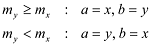
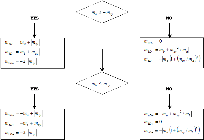
The calculation of the design forces for the plates and shells according to the EC2 algorithm uses the flow diagram in ČSN P ENV 1992–1–1 (731201), Appendix 2, par. A2.8. Following rules are valid for the indices:
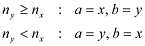
The calculation of the design forces for the walls and shells according to EC2 algorithm uses the flow diagram in ČSN P ENV 1992–1–1 (731201), Appendix 2, par. A2.9. Following rules are valid for the indices:
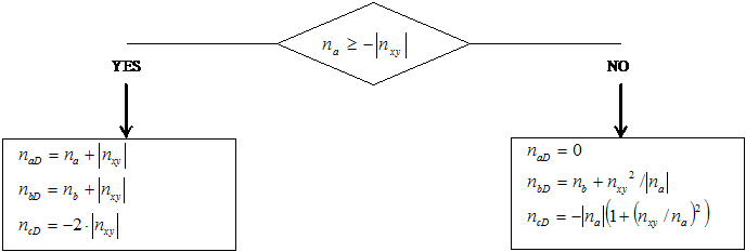
Magnitudes mxD and myD (or nxD and nyD) are the design moments (or forces) in the reinforcement. The negative values of the moments or forces have no practical meaning and they are featured only by reason of integrity.
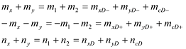
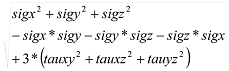
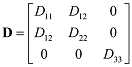
Magnitude mcD (or ncD) is design moment (or force) in the concrete and together with design moments (or forces) in the reinforcement it forms unity triplet with respect to invariant:
The design force in the concrete ncD is used at concrete crushing check (see ČSN P ENV 1992–1–1 (731201), Appendix 2, par. A2.9). The design moments in the concrete mcD are not mentioned in this code, but their meaning is analogical and they are stated by reason of integrity.
The values of the design moments and forces according to „classical“ algorithm are calculated according to the left branches of the flow diagrams stated above, i.e. without respect to the relation between mx, my and mxy (or nx, ny a nxy). This calculation is on the safe side, but in some cases it could be less optimal.
The right branch is used if some of the directions of the reinforcement calculated according to the left branch is pressed (negative value of the correspondent design magnitude). In this case a zero value of the design magnitude is assigned to this direction, and the other direction will have lower value of design magnitude (and consequently lower necessary reinforcement area) than by calculation according to the left branch (the condition of the capacity is granted in both cases). The calculation according to the right branch causes higher pressure in the concrete (magnitudes mcD and ncD) than according to the left banch. By this point of view the EC2 algorithm could be considered as more cost-effective.
2. Stresses, group=3
Basic stresses on 2D
|
Label |
Description |
Calculation |
|
sigxb (not disp.) |
Stress by bending moments |
|
|
sigyb (not disp.) |
Stress by bending moments |
|
|
sigxyb (not disp.) |
Stress by bending moments |
|
|
sigxm (not disp.) |
Stress by normal forces |
|
|
sigym (not disp.) |
Stress by normal forces |
|
|
sigxym (not disp.) |
Stress by normal forces |
|
|
sigx+ |
Stress on positive face |
|
|
sigy+ |
Stress on positive face |
|
|
sigxy+ |
Stress on positive face |
|
|
sigx- |
Stress on negative face |
|
|
sigy- |
Stress on negative face |
|
|
sigxy- |
Stress on negative face |
|
|
tauxz (not disp.) |
Shear stress perpendicular to the plane |
|
|
tauyz (not disp.) |
Shear stress perpendicular to the plane |
|


Principal stresses on 2D
|
Label |
Description |
Calculation |
|
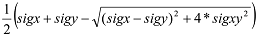
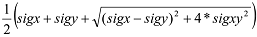
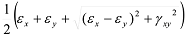
sig1+ |
Principal stress on positive face (max) |
|
|
sig2+ |
Principal stress on positive face (min) |
|
|
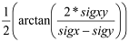
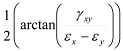
alfa+ |
Angle of principal stress sig1+ |
|
|
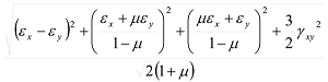
sigE+ |
Equivalent stress on positive face (Mises) |
|
|
sig1- |
Principal stress on negative face (max) |
|
|
sig2- |
Principal stress on negative face (min) |
|
|
alfa- |
Angle of principal stress sig1- |
|
|
sigE- |
Equivalent stress on negative face (Mises) |
|
|
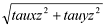
taumaxb |
Maximum shear stress perpendicular to the plane |
|
|
sigZ |
Stress for plane stress |
|
|
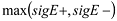
sigEmax |
Maximum equivalent stress (Mises) |
|
|
sigmE |
Membrane equivalent stress (Mises) |
|
|
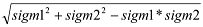
sigm1 |
Principal membrane stress on positive face (max) |
|
|
sigm2 |
Principal membrane stress on positive face (min) |
|
|
alfam |
Angle of principal membrane stress sig1m |
|


Stresses on 3D
|
Label |
Description |
Calculation |
|
sig1, sig2, sig3 |
Principal stresses |
Eigenvalues of stress matrixσ |
|
taumaxB |
Maximum shear stress |
|
|
sigEM |
Equivalent stress (Mises) |
|

Strains, group=14, Plastic strains, group=15
Strains on 2D
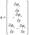
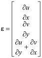
Basic strains are calculated using following formula:

a) Bending strains
 ;
; ;
;  ;
;
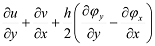
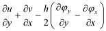
b) Shear strains
 ;
;  ;
;  ;
;
c) Membrane strains
 ;
;  ;
;  ;
;
|
Label |
Description |
Calculation |
|
epsx+ |
Strain on positive surface |
|
|
epsy+ |
Strain on positive surface |
|
|
gamaxy+ |
Slope on positive surface |
|
|
epsx- |
Strain on negative surface |
|
|
epsy- |
Strain on negative surface |
|
|
gamaxy- |
Slope on negative surface |
|
|
eps1+ |
Principal strain on positive surface (max) |
|
|
eps2+ |
Principal strain on negative surface (min) |
|
|
alfa+ |
Angle of principal strain on positive surface |
|
|
eps1- |
Principal strain on negative surface (max) |
|
|
eps2- |
Principal strain on negative surface (min) |
|
|
alfa- |
Angle of principal strain on negative surface |
|
|
epsM+ |
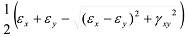
Equivalent strain on positive surface (Mises) |
|
|
epsM- |
Equivalent strain on negative surface (Mises) |
|
|
epsM |
Maximum equivalent strain (Mises) |
|


Strains on 3D
|
Label |
Description |
Calculation |
|
eps1, eps2, eps3 |
Principal strains |
Eigenvalues of strain matrixε |
|
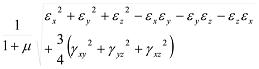
epsM |
Equivalent strain (Mises) |
|
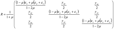
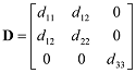
R1, R2, R3 are the eigenvalues of the matrix R: