Displaying the results in named fibres
Named fibres of a cross-section
SCIA Engineer enables the user to name selected fibres of selected cross-sections. These named fibres can be then referred to in the Results service in function Member Stress and the calculated stresses can be displayed in these named fibres.
The standard procedure consists of two steps: (i) naming the required fibres in the Editing dialogue for the selected cross-section, (ii) referring to the named fibres in function Member stress in service Results.
Named items dialogue
The first step is made in the Named items dialogue that consists of the following parts and controls.
|
Cross-section parts |
This window lists all parts of the selected cross-section. For "normal" cross-sections there is just one line here. For composite cross-sections consisting of multiple partial cross-sections the list is longer. |
|
Cross-section fibres |
This window contains all the vertices of the selected cross-section. The list offers the vertices for all the cross-section parts listed in the top window. |
|
Graphical window |
This window shows the graphical representation of the cross-section shape. It also highlights the vertex and/or part that is currently selected in the lists. |
|
[OK] and [Cancel] buttons |
These buttons close the dialogue. [OK] confirms the changes made, [Cancel] abandons them. |
Named fibres in function Results > Member stress
Property window in function Results > Member stress is extended by a couple of options to enable you to refer to the named fibres.
|
Fibres
|
All The stress is displayed in all fibres (i.e. the "envelope" for the stress is displayed) Top The stress is displayed in the top fibres of the cross-section. Bottom The stress is displayed in the bottom fibres of the cross-section. Named fibre You may specify the fibre in which the stress is to be displayed. Note: You must remember the names of the fibres defined in the Named items dialogue as you are required to type the name in the input field. All named fibres The stress diagram is displayed in all fibres that have been given a name in the Named items dialogue. |
|
Cross-section parts |
If the cross-section consists of two or more parts, you may select on which one the stress diagram is to be drawn. Note: You must remember the names of the cross-section parts defined in the Named items dialogue as you are required to type the name in the input field.
|
Procedure to name the fibres
-
Select the required cross-section.
-
Open the Cross-section editing dialogue.
-
In the properties table find item Edit named items and press the three-dot button [...] next to it.
-
The Named items dialogue is opened on the screen.
-
If required, type the names of the cross-section parts (you are not obliged to name all the parts unless you want so).
-
If required, type the names of the selected fibres (you are not obliged to name all the fibres unless you want so).
-
If required, you may:
-
invoke a pop-up menu in the graphical window of the dialogue and employ some basic display-related functions, or
-
use combination "Press-and-hold keys Ctrl+Shift" + "Press-and-hold the mouse right button" and zoom-in or zoom-out the drawing, or
-
use combination "Press-and-hold key Shift" + "Press-and-hold the mouse right button" and move the drawing around the graphical window of the dialogue.
-
-
Confirm the Named items dialogue with [OK].
-
Confirm the Cross-section editing dialogue with [OK].
-
Close the Cross-section manager.
Procedure to display the results in the given named cross-section part
-
You must have the named cross-section parts defined.
-
Select function Beams > Member stress.
-
In the Property table go to item Cross-section parts.
-
Select option Named item.
-
A new input box called Named item is added to the table.
-
Type the name of the required cross-section part.
Note: You must remember the names of the cross-section parts defined in the Named items dialogue as you are required to type the name in the input field.
Procedure to display the results in the named fibre
-
You must have the named fibres defined.
-
Run the calculation and open service Results.
-
Select function Beams > Member stress.
-
In the Property table go to item Fibres.
-
Select option Named item.
-
A new input box called Named item is added to the table.
-
Type the name of the required fibre.
-
Refresh the screen using the action button.
Note: You must remember the names of the fibres defined in the Named items dialogue as you are required to type the name in the input field.
Note: Option Named fibres is of higher priority that the option Named cross-section parts. Therefore, once you select Named fibres in the property table, the item Cross-section parts is hidden.
Example
Let us have a solid rectangular cross-section as in figure below. Further, let us name the fibre number 4 "MY TOP" and fibre number 8 "MY BOTTOM".
Note: The vertex (fibre) numbers are generated automatically by the program and cannot be altered by the user.
Let input a beam fully fixed on both its ends and subject it to the self-weight. The deflection diagram clearly indicates which part of the top and bottom surface of the beam is subjected to tension and which interval of the top and bottom surface is under compression. (Top surface: towards the end tension occurs, in the middle the face is under compression. Bottom surface: it is vice versa).
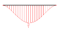
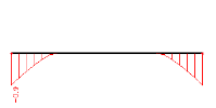
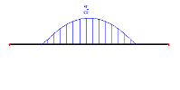
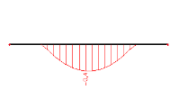
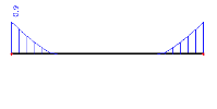
When displaying stress Normal + and Normal- for the user-defined MY TOP and MY BOTTOM fibres, the diagrams look like:
bottom – compression:
bottom – tension:
top – compression:
top- tension:
Note: The named fibres and named cross-sections work for stresses in 1D members only.


