Difference between relative deformations and absolute deformations
The user should be aware about the fact that the steel SLS-check is purely based on relative deformations and not the absolute deformations.
Absolute deformations are the total deformations of the structure element while relative deformations are the deformations relative to a reference line.
Reference lines
As indicated the relative deformations are the deformations relative to the reference line. The reference line represents the 0 values for the relative deformations. How the reference line is constructed depends on the number of activated triangles of the deflection span (def y and def z). There are 2 possible use cases which are explained below.
Reference line for a simply supported span (both ends fixed):
The reference line in case both ends are fixed (= simply supported span) is in essence a line which connects the fixed points (solid triangles) of the buckling system defined for def y and/or def z.
")
Reference line for a cantilever span (one end fixed):
In case there is only one fixed point for the deflection span (= cantilever span): the reference line goes through the fixed point (solid triangle) of the buckling system defined for def y and/or def z and is parallel to the system line of that buckling system.
")
Relative deformations
The relative deformations are in essence the distance in deformation between the reference line and the total deformations. The relative deformations can be obtained in the SLS-check as follows:
- Out of plane deflection (def y):
- uy,max: relative deformation in uy direction due to total loads.
- uy,var: relative deformation in uy direction due to variable loads.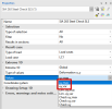

- In plane deflection (def z):
- uz,max: relative deformation in uz direction due to total loads.
- uz,var: relative deformation in uz direction due to total loads.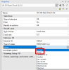

Relative deformation for a simply supported span (both ends fixed):
Below a picture which illustrates graphically how the relative deformation is obtained in case of a simply supported span configuration.
")
Notice that the reference line is constructed between both fixed points (solid triangles) and that the relative deformation is ALWAYS 0mm at these fixed points (solid triangles).
Relative deformation for a cantilever span (one end fixed):
Below a picture which illustrates graphically how the relative deformation is obtained in case of a cantilever span configuration.
")
Notice that the reference line is constructed through the fixed point (solid triangle) and that the relative deformation is ALWAYS 0mm at this fixed point (solid triangle).