Calculation of web weld size
Within SCIA Engineer there is a possibility to choose from two methods for determination of the flange weld sizes by modifying the Weld size determination parameter in the connection setup. (In case of web welds 2nd and 3rd method are recognized as one - based on connection type)
Minimum for full strength
The default calculation of flange weld size is based on the Ref. [35] - ECCS N° 126. The final formula is derived as:
with
Calculation of aw for welded connection
Calculation of the weld size aw is based on the Ref[14], pp.545.
In the section, the moment M is defined by the critical design moment resistance of the connection. The normal force N is taken as the maximum internal normal force in the node, the shear force V is taken as the maximum internal shear force in the node.
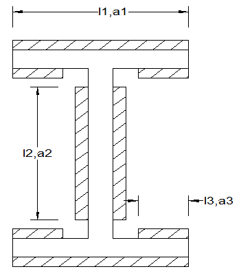
We can define the following properties:
a1 = af
a3 = af
a2 = aw (to be calculated)
l1 = bf
l2 = h –2 tfb –2r
l3 = (bf – twb – 2r) /2


with:
| bf | the beam flange width |
| tfb | the beam flange thickness |
| r | the radius of root fillet |
| twb | the beam web thickness |
| a1 | the weld size a1 |
| a2 | the weld size a2 |
| a3 | the weld size a3 |
| l1 | the length for weld size a1 |
| l2 | the length for weld size a2 |
| l3 | the length for weld size a3 |
| A | the sectional area of the welds |
| I | the moment of inertia of the welds |
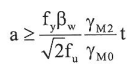
To determine the weld size a2 in a connection, we use a iterative process with a2 as parameter until the Von Mises rules is respected. See Ref.[32] - EN 1993-1-8 Art. 4.5.3.


with:
| fu | the ultimate tensile strength of the weaker part |
| βW | the correlation factor |
| γM2 | the partial safety factor for welds |
Calculation of aw for bolted connection
Calculation of the weld size aw is based on the Ref. [32] - EN 1993-1-8 Art 4.5.3.
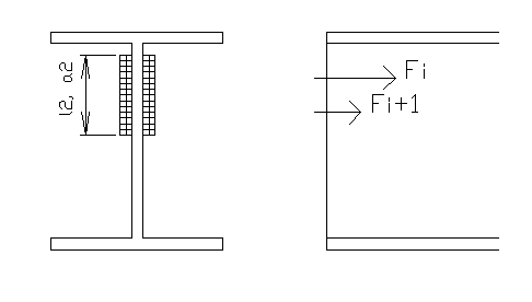
For all possible bolt bolt-rows and groups of bolt-rows, the maximum tension per unit length is calculated. The tension per unit length is calculated as (Fi + Fi+1)/lw.
with:
| Iw | taken as the effective length of non-circular pattern (leff,2) for the considered bolt-row or group of bolt-rows. |
On the weld 2 x l2 x a2, the normal force N =Fi + Fi+1 and the shear force V is acting. The shear force is taken as that part of the maximum internal shear force on the node that is acting on the bolt rows i and i+1. (pure bolt-row ratio- to be checked)
To determine the weld size a2 in a connection, we use a iterative process with a2 as parameter until the Von Mises rules is respected. See Ref.[32] - EN 1993-1-8 Art. 4.5.3. The iteration starts with the weld a2 equal to 1 mm.


with:
| fu | the ultimate tensile strength of the weaker part |
| βW | the correlation factor |
| γM2 | the partial safety factor for welds |
| A | weld area (2*a2*l2) |
In case the option "Calculated using internal forces" is chosen in the connection setup, the T-stub resistances are not calculated and the method used for welded connections is used also for bolted connections.