Check of slenderness
General
Slenderness and limit slenderness of the column should be checked before design and check of reinforcement for column. Using of second order effect in calculation depends on the check of slenderness, because if the check is NOT OK (slenderness is greater than limit slenderness), the second order effect has to be taken into account for column calculation.
| Conditions | Check of slenderness |
Calculation of second order effect |
|
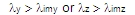
NOT OK | YES |
|
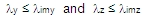
OK | NO |
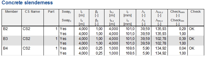
There is service Concrete slenderness in tree Concrete Advanced, where are presented numerical and graphical value of slenderness, limit slenderness , check of slenderness and additional values for their calculation.
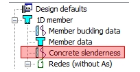
The service for check of slenderness is opened after clicking on the item Concrete slenderness.
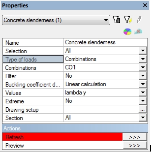
This service is standard service, where user can select:
- which members wants to check (properties Selection and Filters)
- for which loads case/combination/class the members will be done the check (properties Type of loads). The selection of load case/combination/class is necessary, because limit slenderness depends on internal forces. All type of combinations can be evaluated in this service (ULS combination, SLS combination, nonlinear combination...)
- which values will be presented in numerical and graphical output (combo box Values)
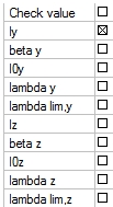
Check value
The ratio of slenderness to limit slenderness
Check value = 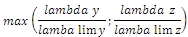
ly(z)
System length around y(z) axis of LCS
beta y(z)
Coefficient for calculation effective length around y(z) axis of LCS
l0y(z)
Effective length around y(z) axis of LCS
Lambda y(z)
Slenderness around y(z) axis of LCS
Lambda lim y(z)
Limit slenderness around y(z) axis of LCS
- How the values will be presented in graphical output (properties Drawing setup and Drawing)
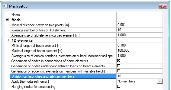
- Positions, in which the numerical and graphical value will be evaluated (properties Extreme and Section). For prismatic member only two values ( at beginning and at the end of member) are presented for each member for extreme = No or Section. For arbitrary member and member with haunch, the member is divided to more parts and the values are presented for each part. Number of parts for dividing can be set in Mesh setup via property Division on haunches and arbitrary members
The buckling coefficient for concrete member can be determinate only from linear calculation, therefore only one item is in combo box Buckling coefficient determinate from. The calculation of buckling coefficient with using stability calculation can be set in Member buckling data after stability calculation.
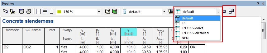
The numerical output is available after clicking on action button Preview. The numerical output does not depend on selected value( is the same for all values).
There is available more detailed tables (for example calculation of limit slenderness according to EN 1992-1-1 ). These detailed tables can be selected after clicking on the header of the table and by selecting the type of the table from the combo box (see picture below)
Existing table can be edit via icon Table composer or via double clicking on the header of the table, see picture above.
The new table can be created via icon Table manager.
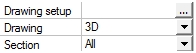
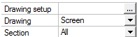
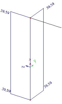
The values in graphical output is always presented around axis of LCS , if the item More comp from combo box Values is not selected. If the item More comp. is selected, then user can select if the values will be presented around local axis (Drawing = 3D) or in one plane (Drawing = Screen)
| Drawing = 3D | Drawing = Screen |
|
|
|
|
Calculation of slenderness
The slenderness (slenderness ratio) is calculated according to clause 5.8.3.2(1) in EN 1992-1-1.
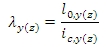
where
l0,y(z) is the effective length of the member (column) around y(z) axis of LCS (perpendicular to y (z) axis of LCS), which can be defined via Member buckling data, chapter Member buckling data.
ic,y(z) is the radius of gyration of the uncracked concrete section in direction of y (z) axis of LCS
The simplified values and formulas for calculation of effective length for isolated columns, braced and unbraced frames are described in clauses 5.8.3.2(2-4) in EN 1992-1-1.
Calculation of limit slenderness
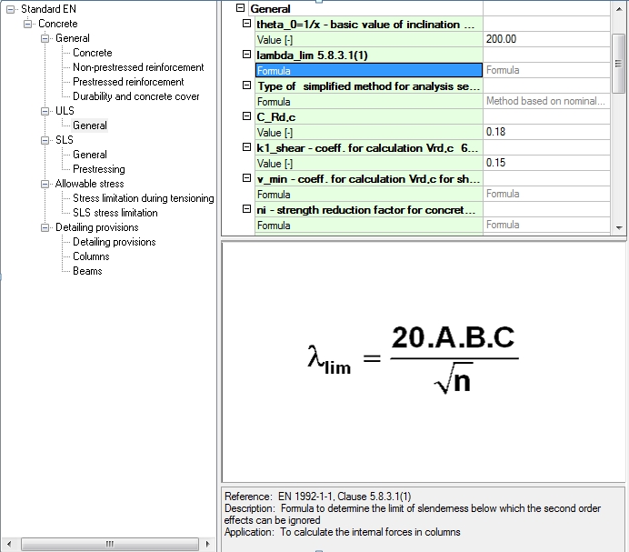
The limit slenderness is calculated according to clause 5.8.3.1(1) in EN 1992-1-1. The limit slenderness and the slenderness are always checked separately for each direction according to 5.8.3.1(2) in EN 1992-1-1. The formula for calculation of limit slenderness in EN 1992-1-1 is national parameter, it means, that different formula, method or value can be used in some countries, see concrete setup ( Manager for national annex > EN 1992-1-1 > General > ULS > General > lambda_lim )
There are changes in calculation of limit slenderness for some national annex see the table below
| National annex | Calculation of limit slenderness |
| Standard EN 1992-1-1 | λ_lim = (20*A*B*C) ⁄ √n |
| DIN EN 1992-1-1 NA |
λ_lim = 25 ... for |n| ≥ 0,41 λ_lim = 16⁄√n ... for |n| < 0,41 |
|
CSN 1992-1-1 NA STN 1992-1-1 NA |
λ_lim = (20*A*B*C) ⁄ √n ≤ 75 |
The limit slenderness calculated according to standard EN 1992-1-1 depends on:
- effective creep ratio feff (coefficient A),
- mechanical reinforcement ratio w (coefficient B),
- shape (ratio) of bending moment rm (coefficient C),
- relative normal force n.
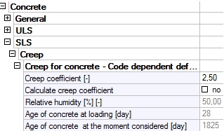
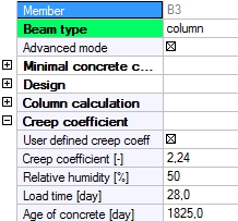
Effective creep ratio
In SCIA Engineer for calculation limit slenderness is used creep ratio loaded from concrete setup (if member data is not defined on column) or concrete member data. It means that if user wants to take into account effective creep ratio according to clause 5.8.4 in EN 1992-1-1, the value of this creep ratio has to be directly input to concrete setup or to concrete member data. Otherwise, the final creep ratio will be taken into account
| Concrete solver > SLS > Creep | Concrete member data |
|
|
The coefficient A is calculated according to formula, where f is creep ratio loaded from concrete setup (if concrete member data is not defined on column) or concrete member data:
A = 1/1+0,2•f.
Mechanical reinforcement ratio
Mechanical reinforcement ratio depends on total area of longitudinal reinforcement. It follows that for design of reinforcement to column and for check of column different mechanical ratio can be taken into account.
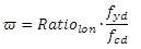
- For design of reinforcement and for calculation limit slenderness in service Concrete slenderness, total area of reinforcement is calculated from ratio loaded from concrete setup (Concrete solver >General > Calculation > column > Advanced setting > User estimate of reinf. for design of reinforcement). The mechanical reinforcement ratio is the same at whole length of the column and it is calculated according to formula:
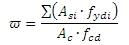
- For checks of columns total area of reinforcement is calculated from inputted reinforcement via REDES or Free bars. The mechanical reinforcement ratio is calculated according to formula below. The mechanical reinforcement can be different at whole length of the column and in each section of the member is calculated according to formula:
where
Ratiolon it is reinforcement ratio loaded from concrete setup (Concrete solver >General > Calculation > column > Advanced setting > User estimate of reinf. for design of reinforcement), see chapter 3.2.6
fyd design yield strength of reinforcement. The quality of reinforcement can be input in Project data or in concrete member data - see chapter Group Design and Group Column calculation, if concrete member data is inputted on checked column
fcd design value of concrete compressive strength
Asi cross-sectional area of i-th reinforcement in the cross-section inputted via REDES or Free bars
fydi design yield strength of i-th reinforcement in the cross-section inputted via REDES or Free bars inputted via REDES or Free bars
The coefficient B is calculated according to formula:
B = √(1+2∙ω)
Shape of bending moment
Shape of bending moment is expressed by ratio of first order end bending moments without influence of imperfection about the selected local axis. The ratio of these moments (value rm) depends on type of member and on shape of shear force.
- if type if member is unbraced around local axis (sway= YES), then rm = 1,0
- if type if member is braced around local axis (sway= NO) and value of shear force perpendicular to local axis is no uniform, then rm = 1,0
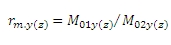
- otherwise, value rm is calculated according to formula
 where
where 
where
M01y(z) it is first end bending moments around y(z) axis of LCS with lesser absolute value as second end bending moment. | M01y(z) |< | M02y(z) | The same values are used for calculation limit slenderness.
M02y(z) it is second end bending moments around y(z) axis of LCS with greater absolute value as first end bending moment. | M02y(z) |≥ | M01y(z) | The same values are used for calculation limit slenderness.
rm.y(z) ratio of bending moment around y(z) axis of LCS which is used for calculation limit slenderness around y(z) axis of LCS
The coefficient C is calculated according to formula:
The value of coefficient C for different cases are presented in table
| Type of column | Bending moment My | Shear force Vz |
Calculation Cy |
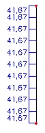
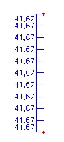
| Unbraced column (sway = YES) without transverse load (Vz is uniform) | 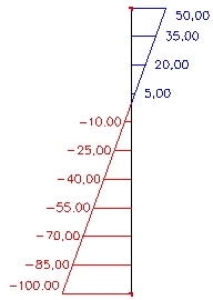
|
|
rm,y = 1,0 Cy = 1,7-1 = 0,7 |
| Braced column (sway = NO) without transverse load (Vz is uniform) | 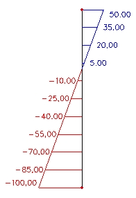
|
|
M01y = 50 kNm M02y = -100 kNm rm.y = M01y/M02y = 50/-100 = -0,5 Cy = 1,7-(-0.5) = 2,2 |
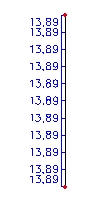
| Braced column (sway = NO) without transverse load (Vz is uniform) | 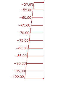
|
|
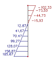
M01y = -50 kNm M02y = -100 kNm rm.y = M01y/M02y = -50/-100 = 0,5 Cy = 1,7-0.5 = 1,2 |
| Braced column (sway = NO) with transverse load (Vz is no uniform) | 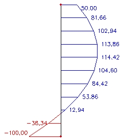
|
|
rm,y= 1,0 Cy = 1,7-1 = 0,7 |
Relative normal force
Relative normal force is calculated according to formula
n = NEd / Ac•fcd
where
NEd design value of the applied axial force in compression
Ac cross-sectional area of concrete
fcd design value of concrete compressive strength
If normal force is not uniform at length of column or the part of the column (for arbitrary member and member with haunch), the maximum value of normal force at length of column or the part of the column will be taken into account.
Output of slenderness
From the previous chapter follows, that different limit slenderness can be used for design of reinforcement and for checks of column.
- The value of limit slenderness for design of reinforcement is presented directly in the service Concrete slenderness and the value is the same at length of column or the part of the column (for arbitrary member and member with haunch).
- The value of limit slenderness used for ULS checks of the column is presented in document of the single check in the services Check response or Check capacity, if the following conditions are fulfilled
- check box Use buckling data is ON in concrete setup or in concrete member data,
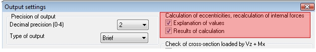
- check box Results of calculation is ON in dialogue Output setting (button Change of setup)
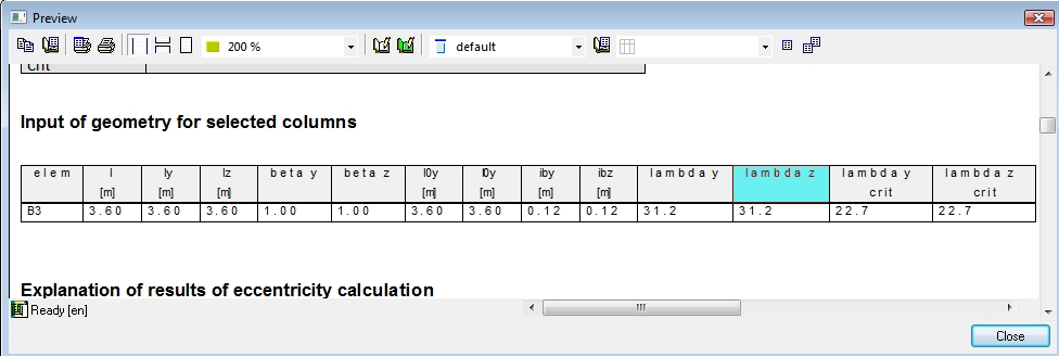
If conditions above are fulfilled, then the table Input of geometry for selected columns is presented in document for single check
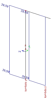
The limit slenderness for ULS check can be different in each section of the beam, because it depends on area of reinforcement, which can be different at length of the column, see table below
| Picture | Slenderness and limit slenderness in the section | |
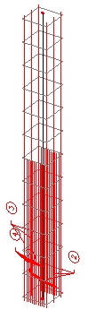
|
Head of the column | 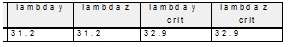
The second order effect will be taken into account |
|
Foot of the column |
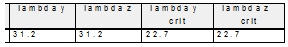
The second order effect will not be taken into account |
|
The value of limit slenderness used for design of reinforcement and ULS checks is the same:
- if inputted user reinforcement via REDES or Free bars is uniform at whole length of the column,
- if ratio of reinforcement set in concrete setup used for design of reinforcement (Concrete solver >General > Calculation > column > Advanced setting > User estimate of reinf. for design of reinforcement) and ratio of user reinforcement is the same, it means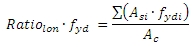
Inputted user reinforcement via REDES of Free bars is not taken into account for calculation of limit slenderness for design of reinforcement.