4.2 Concrete setup for 2D members
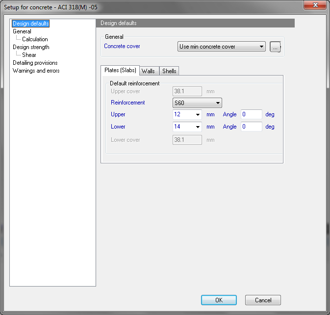
This setup is available from tree Concrete > 2D member > Setup. After clicking on this item the dialog in the picture below is opened
The global setting is divided to the following sheets:
- Design default
- General
- General > Calculation
- Design strength
- Design strength > Shear
- Detailing provisions
Concrete setup can be opened too via action button Concrete setup or via Code setup in the single check
4.2.1 Design defaults
This group is divided into three main parts. It is possible to define minimal concrete cover, set default values for member design, such as reinforcement diameters, and materials both independent for lower and upper reinforcement. It is also possible to define angle of the reinforcement directions.
4.2.1.1 Group General
4.2.1.1.1 Minimal concrete cover
User may choose from two possibilities to determine concrete cover:
4.2.1.1.1.1 User defined concrete cover
By selecting this possibility, program will enable edit boxes for concrete cover, both for upper and lower surface, and user defines his own value to be used.
4.2.1.1.1.2 Use min concrete cover
By this possibility, user let SCIA Engineer to evaluate minimum concrete cover, which may be used according to the Code. Parameters used for this evaluation may be defined in Concrete cover dialog, which is shown below. Here user may redefine type of concrete cover, situation and some more addition to the value due to the corrosive environments.
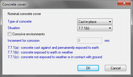
If corrosive environments is used, then final minimal concrete cover value is taken as maximum from two values. One value is given by adding “non-corrosive” value from table 2.1 for imperial unit format system or by table 2.2 for metric unit format system, with the increment for corrosion value, defined by the user. Second value is defined in table 2.3 for all units format systems .
4.2.1.2 Reinforcement
Default value of reinforcement diameters and angles together with default material used are to be defined here. User may define default settings separately for plate, wall and shell members in each of three folders. Design defaults for Plates are shown on the first picture of this chapter.
4.2.2 General
Please see the chapter "4.1 Concrete setup for 1D member".
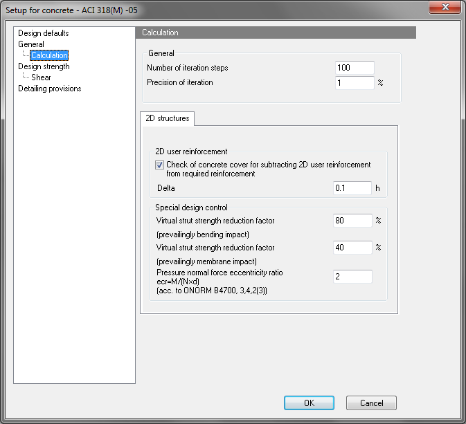
4.2.3 General > Calculation
The user can set general parameters for calculation of 2D members and special parameters for calculation and design reinforcement.
4.2.3.1 Group General
Here, it is possible to define parameters, which will be used for 2D members.
4.2.3.1.1 Number of iteration steps
|
Group |
General > Calculation |
|
Type of parameter |
Edit box |
|
Default: |
100 (Limit values from 1 to1000) |
|
Local setting |
NO |
|
Influence |
All iterative calculation in concrete design |
This setting is used for iterative calculation in concrete. If iterative calculation does not finish after reaching number of steps, the calculation is finished. In this case, the result will not be presented and user has to make some changes in calculated structures or decrease precision of iteration (see chapter "4.1 Concrete setup for 1D member") or increase number of iteration steps.
4.2.3.1.2 Precision of iteration
|
Group |
General > Calculation |
|
Type of parameter |
Edit box |
|
Default: |
1% (Limit values from 0.0001 to10) |
|
Local setting |
NO |
|
Influence |
All iterative calculation in concrete design |
This setting is used for iterative calculation in concrete. Iterative calculation is finished is difference of results of two consecutive iteration steps is lesser than this precision . If iterative calculation does not finish after reaching number of steps, the calculation is finished. In this case, the result will not be presented and user has to make some changes in calculated structures or decrease precision of iteration (or increase number of iteration steps (see chapter "4.1 Concrete setup for 1D member").
4.2.3.2 2D Structures
4.2.3.2.1 Group 2D user reinforcement
Normally, additional reinforcement, if needed, is calculated as simple difference between required and user defined reinforcement. User may come across two possible situations when this is declined:
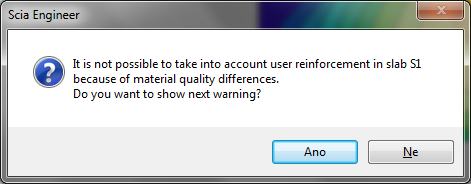
- If there is already defined practical reinforcement (the one, which physically exist in the model), which has different material, than the material defined in Member data or in Project settings. If this happens, then user will be warned by error message below and this user reinforcement is not recognized.
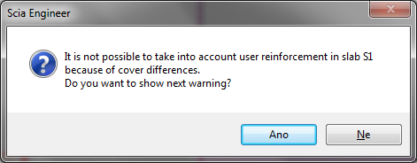
- Second situation may happen, when user has also practical reinforcement defined on the member and has activated the possibility “Check of concrete cover for substracting 2D user reinforcement from required reinforcement”. When this check box is activated, new input parameter is enabled and user may define required value. All reinforcement layers within this range will be ignored by the design. The error dialog is also displayed and design will end up in same results as in the first case.
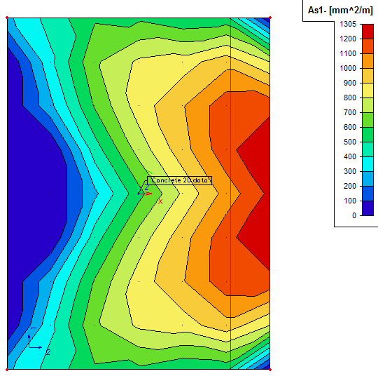
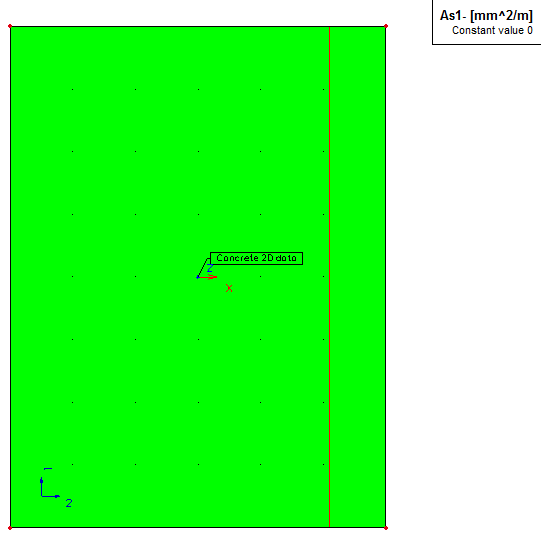
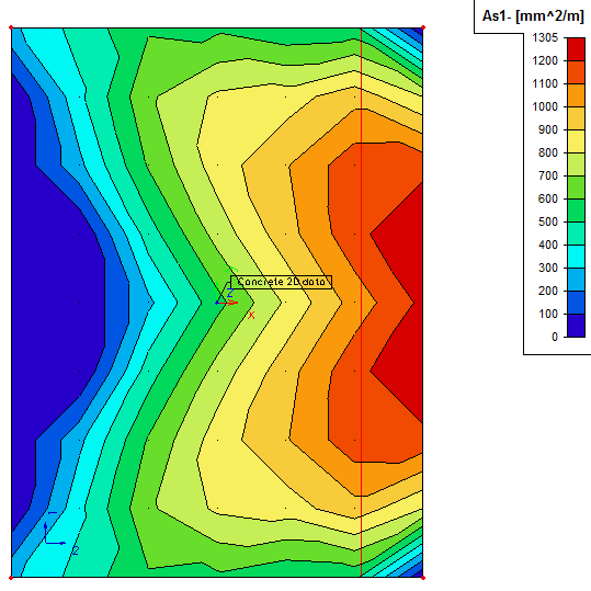
Let’s demonstrate this on an example, when only main reinforcement on the whole slab was defined. There is diameter of 12mm used and the distance between the bars is set to 100mm. We can change the material of this reinforcement polygon for example to B500A contrary to B400A, which is defined in member data for first option. Then we will get these results:
|
Required reinforcement |
User reinforcement |
|
|
|
|
Additional reinforcement |
Total reinforcement |
|
|
|

4.2.3.2.2 Group Special design control
4.2.3.2.2.1 Virtual strut reduction factor
This is special design control parameter used in the virtual strut design. The actual (non-reinforced) concrete strength in a 2D continuum being cracked by prevailingly bending impact is factorised (reduced) by this coefficient: fy’ → fy’ × value/100. Input default is set to 80% (see the NEDIM handbook 2D Reinforced Concrete Design – Theoretical Background). Values less than 100have physical sense only (100 % = full concrete strength).
4.2.3.2.2.2 Virtual strut reduction factor [%] –
This is special design control parameter used in the virtual strut design. The actual (non-reinforced) concrete strength in a 2D continuum being cracked by prevailingly membrane impact is factorised (reduced) by this coefficient: fy’ → fy’ ×value/100. Input default acc. to ACI 318M-05, §19.2.11, is set to 40%. Values less than 100has physical sense only (100 % = full concrete strength).
4.2.3.2.2.3 Pressure normal force eccentricity ratio
Limit eccentricity ratio of axial force in Shell design (General XYZ projects). No meaning for structural systems Wall & Plate (Plate XY or Wall XZ projects). Input default value is set to 2,0 (design recommendation acc. to ÖNORM B 4700, §3.4.2(3)
Hint: If the real value of ecr exceeds the value on input, the stress-strain state is considered as “prevailing bending”
4.2.4 Design strength
In this tab-sheet are parameters, which have influence directly to calculation design strength of the structure
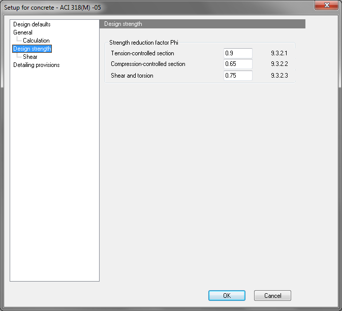
4.2.4.1 Group Strength reduction factor Phi
Design strength of the structure is calculated multiplying the nominal strength by a strength reduction factor φ. The values of this factor for different situation are defined in ACI-318-05, clause 9.3.2. In these user can define default value of strength reduction factor for basic situation.
4.2.4.1.1 Compression controlled section
|
Group |
Design strength > Strength reduction factor Phi |
|
Type of parameter |
Edit box |
|
Default: |
0.65 |
|
Local setting |
Yes |
|
Influence |
Calculation strength reduction factor for design of longitudinal reinforcement |
This factor should be used for calculation if tensile strain in reinforcement (value εt) is lesser than 0.002. It is also used for calculation new strength reduction factor for transition zone, when ε value is 0.005>εt >0.002.
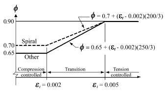
Only strength reduction factor for other type of reinforcement is defined, because design of spiral reinforcement is not supported.
4.2.4.1.3 Shear and torsion
|
Group |
Design strength > Strength reduction factor Phi |
|
Type of parameter |
Edit box |
|
Default: |
0.75 |
|
Local setting |
Yes |
|
Influence |
Calculation strength reduction factor for design of shear reinforcement |
This factor is used for calculation design shear strength.
4.2.5 Design strength > Shear
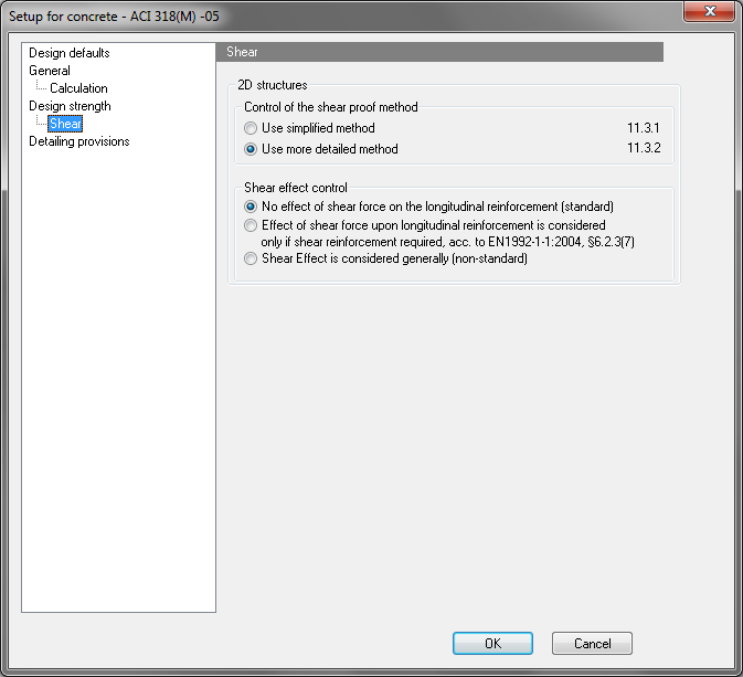
4.2.5.1 Group 2D structures
4.2.5.1.1 Control of the shear proof method
This is parameter for control of the shear proof method for Shells and Plates models according to the §11.3 of the Code. It determines, whether the shear strength provided by concrete non-prestressed members is sufficient or if shear reinforcement is required. User may choose from two possibilities.
4.2.5.1.1.1 Use the simplified method acc. to §11.3.1
For determination of the limiting value of concrete strength, formula according to the §11.3.1, including the condition Vc = 0 (§11.3.1.3) for over tensioned cross-sections, will be used. This is called simplified method.
4.2.5.1.1.2 Use more detailed method acc. to §11.3.2
For determination of the limiting value of concrete strength, formula according to the §11.3.2 will be used. This is called detailed method.
4.2.5.2 Group Shear effect control
This is code independent parameter, which allows user to control effect of shear force on longitudinal reinforcement. User may choose from three possibilities.
4.2.5.2.1 No effect of shear force on the longitudinal reinforcement
This option is set as input default. No effect of shear force on the longitudinal reinforcement is considered (ACI 318M-05 standard).
4.2.5.2.2 Effect of shear force upon longitudinal reinforcement is considered only if shear reinforcement required
Effect of shear force upon longitudinal reinforcement is considered in Shear Region 2 (regions, where shear reinforcement is needed from the static point of view) according to the EN 1992-1-1:2004, §6.2.3(7)
4.2.5.2.3 Shear Effect considered generally
Effect of shear force upon longitudinal reinforcement is considered both in Shear Regions 1 & 2 (on every region). This is non-standard method.
4.2.6 Detailing provisions
Sometime amount of statically needed reinforcement is not determining for finally designed reinforcement and different checks come in place. These checks may be switched off/on or adjusted in concrete setup dialog in Detailing provisions.
4.2.6.1 2D members
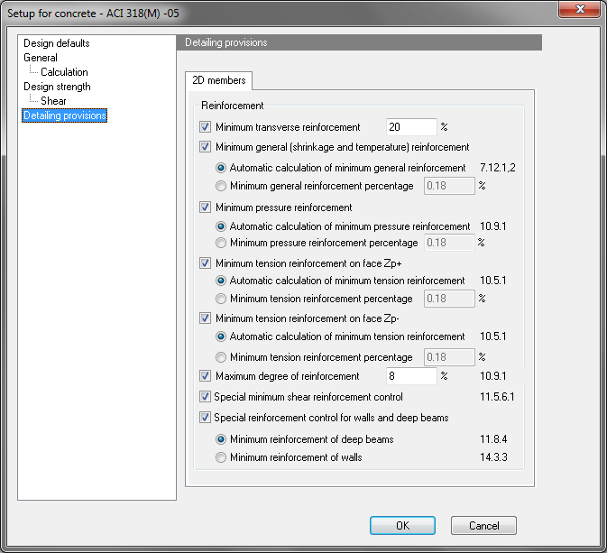
4.2.6.1.1 Minimum transverse reinforcement
Minimal amount of transverse reinforcement, determined as a percentage of main reinforcement. SCIA Engineer recognizes the main direction and then add a requirement of minimal amount of reinforcement for transverse direction to be compared with statically needed reinforcement.
Default value = 20%.
4.2.6.1.2 Minimum general (shrinkage and temperature) reinforcement
Minimum percentage of longitudinal reinforcement, designed for shrinkage and temperature reasons.
4.2.6.1.2.1 Automatic calculation of minimal general reinforcement
According to the §7.12.1,2 of the ACI Code minimum reinforcement should be designed for shrinkage and temperature reasons.. The required value is dependent of steel grade used in the member. The minimum amount is applied to a gross concrete area. (both surfaces together)
4.2.6.1.2.2 Minimum general reinforcement percentage
Direct percentage of gross concrete area. The minimum amount is applied to a gross concrete area. (both surfaces together)
Default value = 0,18%.
4.2.6.1.3 Minimum pressure reinforcement
Minimum percentage of longitudinal reinforcement, designed for compression members.
4.2.6.1.3.1 Automatic calculation of minimal pressure reinforcement
According to the §10.9.1 of the ACI Code, minimum reinforcement area of longitudinal reinforcement, for noncomposite compression members, shall be not less than 1%. The minimum amount is applied to a gross concrete area. (both surfaces together)
4.2.6.1.3.2 Minimum pressure reinforcement percentage
Direct percentage of gross concrete area. The minimum amount is applied to a gross concrete area. (both surfaces together)
Default value = 0,18%.
4.2.6.1.4 Minimum tension reinforcement at face +Zp
Minimum percentage of tension reinforcement at the surface with positive Z coordinate (in the local coordinate system of the 2D member). This check has two options.
4.2.6.1.4.1 Automatic calculation of minimal tension reinforcement
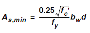
According to the §10.5.1 of the ACI Code, at every section of a flexural member where tensile reinforcement is required by analysis, reinforcement provided shall not be less than that given by formula bellow. The minimum amount is applied to a specific surface and direction. Amount given by the formula shell not be less than 1.4bwd/fy.
4.2.6.1.4.2 Minimum tension reinforcement percentage
Direct percentage of a concrete area. The minimum amount is applied to a specific surface and direction.
Default value = 0,18%.
4.2.6.1.5 Minimum tension reinforcement at face -Zp
Minimum percentage of tension reinforcement at the surface with negative Z coordinate (in the local coordinate system of the 2D member). This check has two options.
4.2.6.1.5.1 Automatic calculation of minimal tension reinforcement
According to the §10.5.1 of the ACI Code, at every section of a flexural member where tensile reinforcement is required by analysis, reinforcement provided shall not be less than that given by formula bellow. The minimum amount is applied to a specific surface and direction. Amount given by the formula shell not be less than 1.4bwd/fy.
4.2.6.1.5.2 Minimum tension reinforcement percentage
Direct percentage of a concrete area. The minimum amount is applied to a specific surface and direction.
Default value = 0,18%.
4.2.6.1.6 Max degree of reinforcement
According to the §10.9.1 of the ACI Code, maximum reinforcement area of longitudinal reinforcement, for noncomposite compression members, shall be not more than 8%.
Default value = 8%.
4.2.6.1.7 Special reinforcement control for walls and deep beams
4.2.6.1.7.1 Minimum reinforcement of deep beams
According to the §11.8.4 of the ACI Code, the area of shear reinforcement perpendicular to the flexural tension reinforcement, shall not be less than 0.0025bws, and s shall not exceed the smaller of d/5 and 300 mm. Value d/5 is represented as height of the member.
4.2.6.1.7.2 Minimum reinforcement of walls
According to the §14.3.3 of the ACI Code, minimum vertical and horizontal reinforcement shall be placed in the member unless a greater amount is required from other article. The area is given as percentage of a gross concrete area. The required value is dependent of steel grade and size of the diameter used in the member. The minimum amount is applied back to a gross concrete area. (both surfaces together)
4.2.6.1.8 Special minimum shear reinforcement control
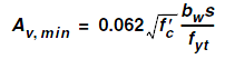
A minimum area of shear reinforcement, Av,min , shall be provided in all reinforced concrete flexural members (prestressed and nonprestressed) where Vu exceeds 0.5φVc. If check is OFF, then no minimum shear reinforcement is provided for Vu > 0.5ΦVc (standard provision §11.5.6.1), If check is ON minimum shear reinforcement is provided for Vu > 0.5ΦVc by §11.5.6.3, and Av,min for prestressed (except as provided in 11.5.6.4) and nonprestressed members shall be computed by formula bellow, but should not be less than (0.35bws)/fyt.