5.4 System lengths and buckling settings
This buckling setting (= Buckling group BG) can be defined via the 1D-member property "System lengths and buckling settings" and contains all the buckling related settings for that buckling system.
There is supported following possibilities for calculation effective length factor in ACI code:
- Calculate
- Factor
- Length
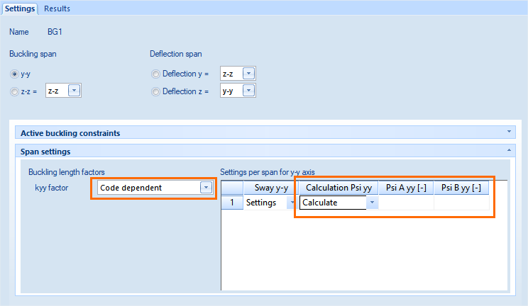
- Code dependent – it is a special calculation according to clause 10.12.1 in ACI 318-05.
Calculation of the effective length factor for the method Code dependent (according to code ACI 318-05) is described in the next chapter
The important parameter for calculation of buckling data is type of structure (braced or unbraced). The global type of structure can be set in concrete setup (tree Concrete > Design default > Design default > Default sway type (for columns and beams only)), see chapter "4.1 Concrete setup for 1D member". For example , the structures is braced perpendicular to y axis of GCS , if check box y-y is OFF (it means the structure is not prone to sway perpendicular to y axis)
5.4.1 Code dependent calculation of buckling coefficients
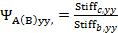
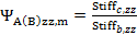
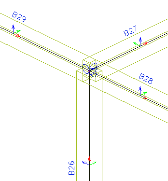
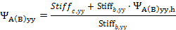
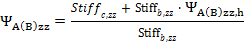
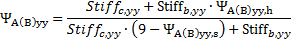
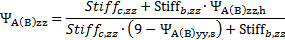
The effective length factor can be calculated according to clause 10.12.1 in ACI 318-05. The calculation of this factor depends on ratio of stiffness of compression members to a flexural members in plane, which are joined to head ( ψAy(z)) and foot ( ψBy(z)) of calculated compression member. These ratios can be input directly by the user via columns Psi A yy(zz) and Psi B yy(zz) (if Calculation Psi yy(zz) = Input ) or can be calculated automatically by the program (if Calculation Psi yy(zz) = Calculate )
Automatically calculation of these ratios depends on, if :
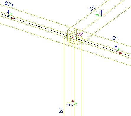
- some beams are linked to head or foot of column (compression member)
- some standard support is defined at head or foot of column (compression member)
- some hinges are defined at head or foot of column (compression member) or in linked beams
- some 2D member is defined at head or foot of column (compression member)
The way of calculation for different cases is in table below:
 ,
, 
 ,
, 


 ,
, 
If the compression member is linked to the 2D member, hinges defined at the head or foot of column are not taken into account for calculation value ψ ( value is always 0)
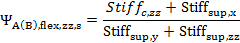
The value ψ for only members linked to the to head and foot of compression member is calculated according to clause 10.12.1 in ACI 318-05. In other cases the equations for calculation ψ was determined by analytic study and the value ψ is only approximate value. Therefore for more complicated cases the user value of ψ should be inputted.
Stiffness of flexible support and flexible hinge for rotation in US format in direction of local axis has to be recalculated to radian. It means that unit for this stiffness has to be kpi·in/rad
Stiffness of flexible support and flexible hinge in direction of local axis has to be recalculated to unit area. It means that unit for this stiffness has to be MN·m or kpi·in
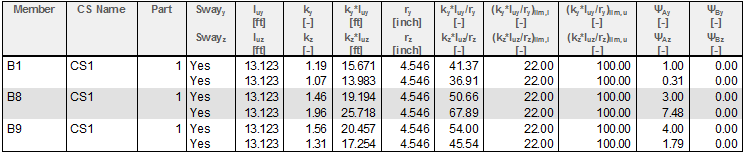
The values ψ about both axis’s and in head and foot of compression member are presented in numerical output of the service Concrete slenderness
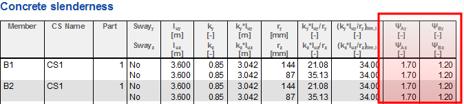
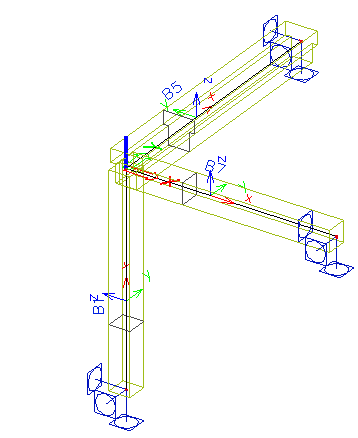
In the tables below are calculations of value ψ in SEN and by manually calculation for three cases provided that orientation of GCS and local coordinate system is following:
- axis X in GCS = axis Z in LCS of compresion member
- axis Y in GCS = axis Y in LCS of compresion member
- axis Z in GCS = axis X in LCS of compresion member
|
Result from SEN (service Concrete slenderness) |
|---|
|
|
|
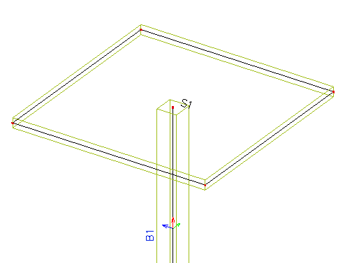
Member B1 (only beams are linked to head and foot of compression member) |
|
|
|
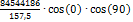
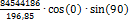
Input data: Compression member (B1): Iy = Iz = 5125,35 inch4, E = 4032 ksi, redc = 1 (EIy)c =(EIz)c = 20665411 kip·inch2, lc = 13,123 ft Flexural member (B7): Iy = Iz = 5125,354 inch4, E = 4032 ksi; redb = 1 (EIy)b = 20665411 kip·inch2, lc = 13,123 ft α = 180 deg; β = 0 deg Flexural member (B5): Iy = 20968,3 inch4, E = 4032 ksi; redb = 1 (EIy)b = 84544185.6 kip·inch2, lc = 16,404 ft α = 90 deg; β = 0 deg
|
|
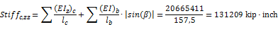
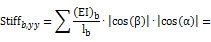
Calculation:
|
|
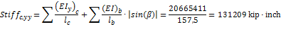
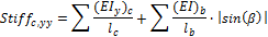
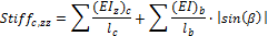
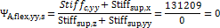
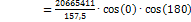 +
+ =131209kip· kip·inch
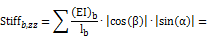
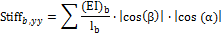
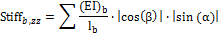
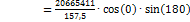 +
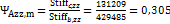
+ =429485 kip·inch
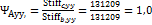 ;
; 
|
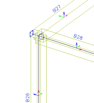
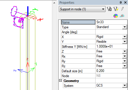
Member B8 (only standard support at head and foot of column) |
|
|
|
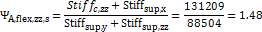
Input data: nsup,yy = 2 (support in direction z-axis of LCS [X=Rigid] and bending support about direction z-axis of LCS [Ry=Rigid] of compression member are rigid) nsup,zz = 1 (support in direction y-axis of LCS [Y=Flexible] of compression member is flexible) Stiffsup,x = 0 because [Z=Free] Stiffsup,y =Stifness Y=57,1kip/inch = 88504,8 kip·inch because[Y=Flexible] Stiffsup,z= 0 because [X=Rigid] Stiffsup,yy = 0 because [Ry=Rigid] Stiffsup,zz =0 because [Rx=Free]
|
|
Calculation:
|
|
 =3
=3
|
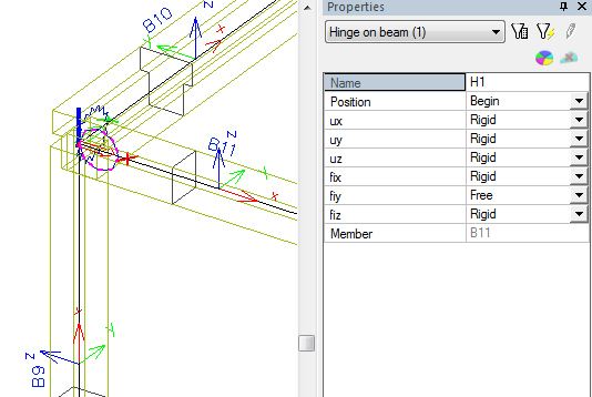
Member B9 (Only hinges defined at head or foot of column or in linked beams) |
|
|
|
Input data: nhin,yy = 2 (hinge in direction z-axis and in direction of x –axis of LCS of compression member are rigid) nhin,zz = 3 (hinge in direction y-axis and in direction of x –axis of LCS of compression member are rigid and hinge about direction z-axis of LCS] of compression member is flexible ) Stiffhin,x = 0 because [uz=Rigid for B10 and B11] Stiffhin,y = 0 because [ux=Rigid for B10 and uy=Rigid for B11] Stiffhin,z= 0 because[uy=Rigid for B10 and ux=Rigid for B11] Stiffhin,yy = 0 because [fix=Rigid for B10 and fiy=Free for B11] Stiffhin,zz =1544kipinch/deg = 88465 kipinch/rad because [fiy=Flexible for B10 and fix=Rigid for B11] |
|
Calculation:
|
|
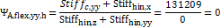
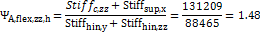
 =3
=3 =1.48
=1.48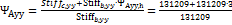 =4
=4 1,79
1,79