Concrete – Automatic member reinforcement design (AMRD)
Autodesign of concrete section is the same part as the Reinforcement design performed in the service Concrete Advanced > Automatic member reinforcement design > Reinforcement design
Autodesign in Concrete Advanced service
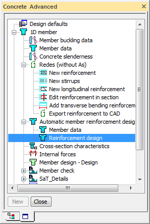
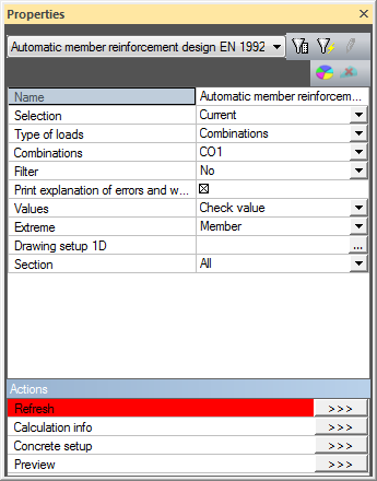
When the user clicks on action button Refresh then the same procedure of Autodesign is performed. For concrete cross-section the procedure is called Automatic Member Reinforcement Design (AMRD). The non-prestressed reinforcement is designed in selected beam. Both longitudinal reinforcement and stirrups are designed.
Theoretical background for AMRD
The non-prestressed reinforcement in beams can be defined manually by the user or it can be calculated automatically by the program.
The latter designs the reinforcement on the basis of parameters defined in:
- reinforcement template,
- setup dialogue of service Concrete Advanced,
- member data related to the automatic design,
- practical reinforcement defined manually.
The automatic design takes into account the combination of bending moments and axial force and shear forces. It does not include torsion and deflections. It works within the ultimate limit state. The automatic design can be used for loads cases, ULS (not SLS) combinations and classes with ULS or ULS+SLS combinations. Concerning the parameters mentioned above, the practical reinforcement is of the highest priority. That means, if some reinforcement has been defined, the automatic design uses in the first step the diameter of this practical reinforcement. There is no output to the document. The results of the automatic design can be reviewed only on the screen in the graphical window and/or in the Preview window. Of course, the bill of reinforcement can be inserted into the document in order to show the reinforcement that has been automatically designed. The automatic design uses only the layers of the reinforcement marked in the reinforcement template. The automatic design is not capable of adding a new layer in the situation when the required reinforcement cannot be put into just one layer. Therefore, it may happen that the automatic design can fail.
The basic procedure is the following:
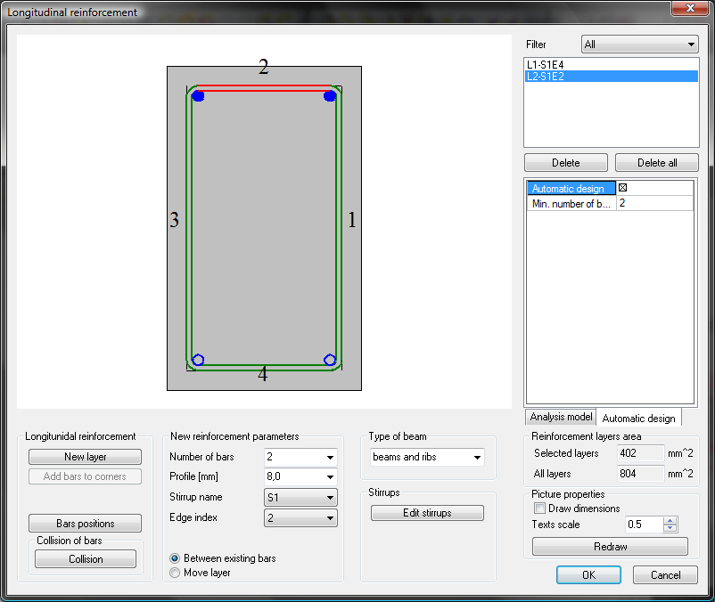
- First, the parameters that may affect the automatic design should be defined. It is necessary to define reinforcement template for longitudinal reinforcement, which layers can be optimise during the automatic reinforcement procedure,
- Specify the default parameters in
- Setup dialogue of service Concrete Advanced affecting and controlling the procedure for the automatic design,
- member data related to the automatic design, if required. These data overwrites the default values by member data that are specific for a particular beam.
- During Autodesign the standard design of reinforcement for combination N+My+Mz is performed (maximal bending moments along whole member are considered for design of reinforcement). The maximal amount of upper and lower reinforcement is designed.
- The designed reinforcement template is used for checks (Interaction diagram, detailing provisions). The calculation is evaluated based on the maximal utilisation (check value) in concrete setup. When the calculated check value is still less than the defined utilisation, then bars are deleted to achieve the optimal utilisation.
Template preparation
The template used for the Autodesign is prepared in a standard way. One difference is that the check box Automatic member design is switched ON.
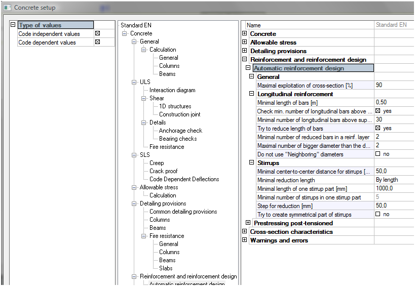
Concrete setup
The default settings used for Autodesign are stored in Concrete setup.
Member data for the automatic reinforcement design
The member data used for AMRD looks like this:
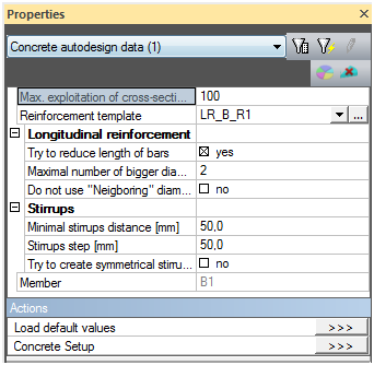
General
|
Max. exploitation of cross-section |
Specifies the maximal utilisation of the cross-section in the automatically reinforced beam. The value may be between 1 and 100%. |
|
Reinforcement template |
Shows the used reinforcement template. Note: This item appears in the dialogue ONLY when the already defined member data are edited. If the member data are being assigned to a new member, this item is not accessible. |
Longitudinal reinforcement
Stirrups
|
Minimal stirrups distance |
Specifies the minimal distance between stirrups measured from the centre of a bar to the centre of an adjacent bar. |
|
Stirrups step |
Defines the step for the reduction of the distance between two adjacent stirrups. This ensures that the distance between stirrups is always a "rounded" number – e.g. 200 mm, then 250 mm, then 300 mm, etc. (and not e.g. 200, 246 mm, 298 mm, etc.). |
|
Try to create symmetrical stirrups parts |
This parameter may enforce that the stirrup parts are symmetrical along the length of the beam. |
|
Member (informative only) |
Shows the name of the beam where the member data are assigned to |
Illustrative example
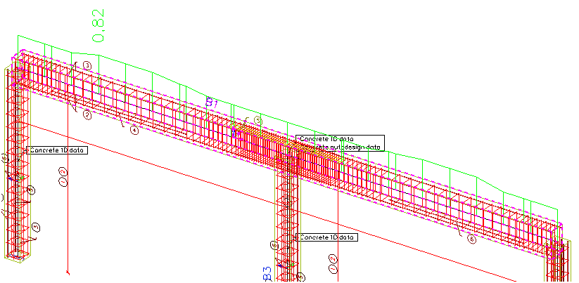
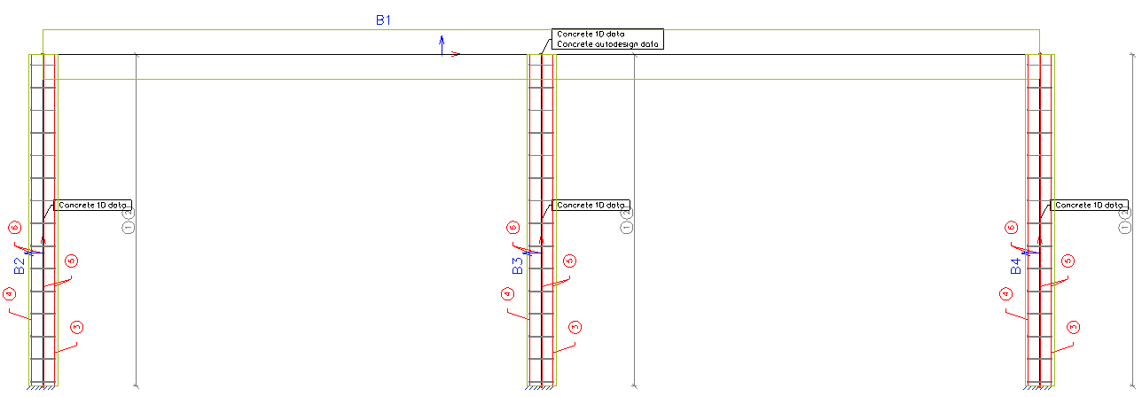
Let us consider a very simple example of concrete frame. The structure is subjected to several loads (self weight, permanent, variable, wind etc.). The aim of this example is to find the optimal reinforcement pattern in the continuous horizontal member of the frame.
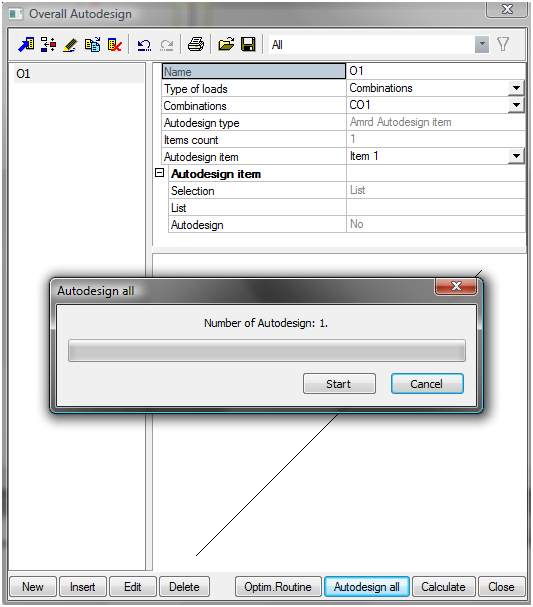
One Autodesign function with type AMRD Autodesign is defined and reinforcement pattern for beam B1 is optimized. No additional settings related to parameters are defined for this case. Possibly AMRD data can be defined on the beam only.
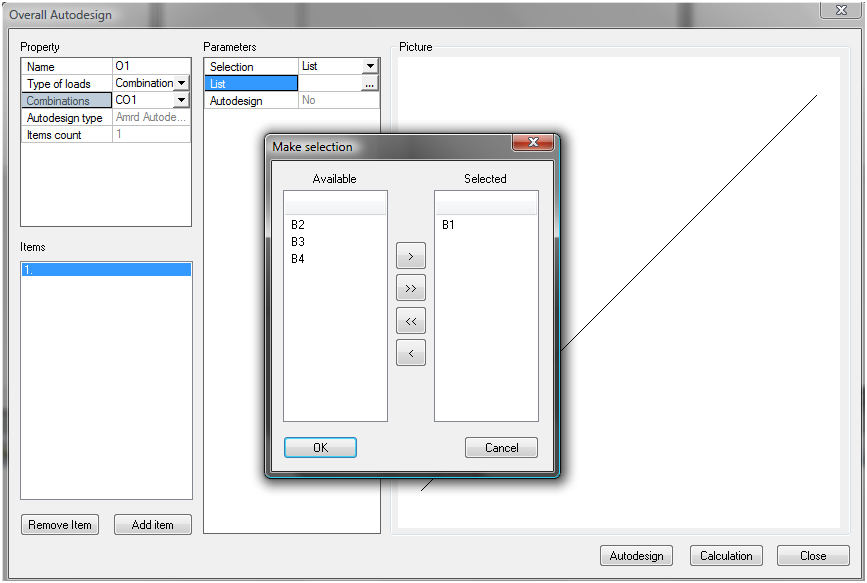
Autodesign starts after pressing button Autodesign all.
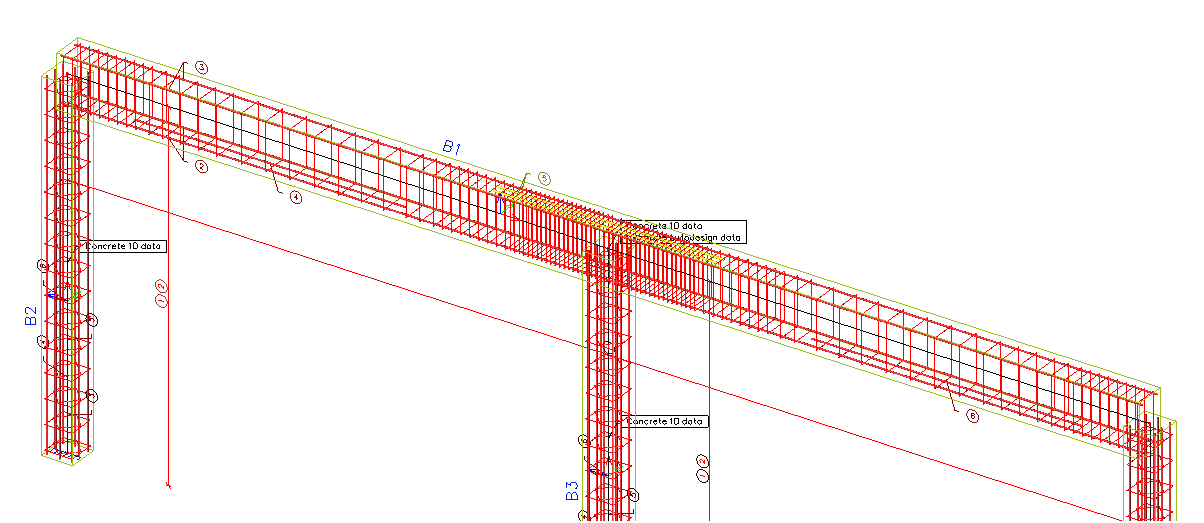
The obtained results of designed reinforcement for beam B1 are the following. The reinforcement is automatically designed and input on beam B1. You can see higher density of stirrups near the supports and additional longitudinal bars in the span and above the middle support.
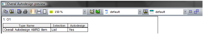
The document output is very simple.
The results can be verified in the standard concrete checks:
- Check capacity (max check value 0,97)
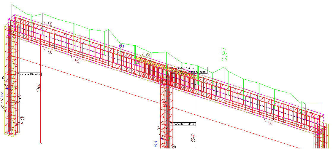
- Detailing provision (max check value 0,82)