XML update example
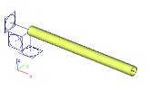
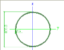
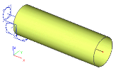
Let us have a project named Cantilever.esa with a simple cantilever beam of a circular cross-section.
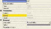
The dimensions of the cross-section are defined through two parameters: Diameter and Thickness.
Both the parameters are of type Cross-section length (Css length) and their initial values are 200 mm and 5 mm.
Now we have to open the XML file editor (tree menu function Tools > XML).
There we have to create a new "XML document" containing the table of defined parameters.
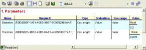
To do so, we add the table Libraries > Parameters.
The inserted table looks like this:
The created XML document must be exported into XML file. This can be achieved through function Export (available on the toolbar of the preview window in the XML file editor).
The generated XML file (named CantileverParameters.xml) looks like:
|
XML file |
Comment |
|
<?xml version="1.0" encoding="UTF-8" standalone="yes" ?> -<projectxmlns="http://www.scia.cz"> <defuri="CantileverParameters.xml.def" /> -<container id="{5C62EA11-86D4-11D4-B3AB-00104BC3B531}"t="EP_Parameters.EP_Param.1"> -<table id="B4DDEC1E-5869-4B8C-8B4B-1A8C07B76699"t="EP_Parameters.EP_Param.1"> -<h> <h0t="Name" /> <h1t="UniqueID" /> <h2t="Type" /> <h3t="Evaluation" /> <h4t="Use range" /> <h5t="Value" /> </h> |
|
|
-<obj id="1"nm="Diameter"> <p0v="Diameter" /> <p1v="{FDD9298F-1A51-406B-9887-8C9302981A47}" /> <p2v="11"t="Css length" /> <p3v="0"t="Value" /> <p4v="0" /> -<p5 t=""> -<h> <h0t="Real" /> </h> -<row id="0"> <p0v="0.2" /> </row> </p5> </obj> |
Parameter Diameter
value = 0.2 m |
|
-<obj id="2"nm="Thicknes"> <p0v="Thicknes" /> <p1v="{9E8E662D-4B12-43EE-8A56-A33948D079A1}" /> <p2v="11"t="Css length" /> <p3v="0"t="Value" /> <p4v="0" /> -<p5 t=""> -<h> <h0t="Real" /> </h> -<row id="0"> <p0v="0.005" /> </row> </p5> </obj> |
Parameter Thickness
value = 0.005 m |
|
</table> </container> </project> |
|
We will not explain the meaning of every single line of the XML document. The example above demonstrates the structure of the XML file and shows the way the two parameters from our example are stored.
Note: When the export function is invoked, the XML file editor generates in fact two files: XML file and the corresponding definition file (DEF file). For example, if the name of the XML file is MyFile.XML, the name of the definition file is MyFile.xml.DEF. Briefly said, the definition file contains the definition of all the characteristics that are referred to in the XML file.
Manual XML update
And now, we may demonstrate the principle of the XML update function. Let us assume that we have a tool that can read and modify the XML file. Using this tool we can change the value of the parameters in the XML file. Let us assume that the value of the Diameter was changed to 0.8 m.
Note: Later we will show how exactly this can be done. For the time being, let us take it for granted that the tool changed the XML file and modified parameter Diameter.
Let us go back to SCIA Engineer where our original project is still open. Call function File > Update > XML file and browse for our modified file.
The program updates the data of the project (in our example - the values of the parameters) and we can see the result on the screen. The tube has increased its diameter four times.
Automatic XML update
Now, let us return to the idea of an external tool that is capable of modifying the XML file.
Probably every engineering office uses a kind of spreadsheet processor such as MS EXCEL. Taking into account the fact that the Microsoft’s product is probably the most widespread tool available in the market, we will use it in our example.
List of operations carried out by the EXCEL application
The EXCEL "application" will do the following operations:
-
it will take our input of the diameter and thickness of the cross-section,
-
it will generate the appropriate XML file,
-
it will open the SCIA Engineer project with the cantilever in question,
-
it will update the cross-section using the values from the generated XML file,
-
it will generate output document containing the calculated deformation of the cantilever,
-
it will show the vertical displacement of the free end of the cantilever directly in the EXCEL sheet.
Note: The EXCEL application could naturally display also other results. In the interests of brevity, clarity, and comprehension, we will deal in our example just this single result value.
We will prepare a VBA script (run from a XLS sheet) that will perform all the described operations. SCIA Engineer as a calculation engine will be running "somewhere" on the background. The user won’t even spot it on the screen and will be able to think that the EXCEL sheet itself does everything.
To start with, we have to pre-prepare something in SCIA Engineer.
First, we have to generate the .XML "template" file and the corresponding .DEF file. This was already done earlier in our example and we can simply take the produced .XML file. Unless we decide to use different folder (different then SCIA Engineer project folder) for our EXCEL application, we do not have to bother about the .DEF file. It will be in the right place by default.
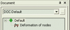
Second, we have to create a document in our SCIA Engineer project. The document must contain the table with calculated nodal displacements. The project must be then saved.
Let us now start MS EXCEL, create a new document and define two sheets. Let us name them "Table" and "XML". The first one (Table) will be our "User interface", i.e. it will be the sheet that will be used by the user. The other one (XML) will be used as an auxiliary sheet to hold the contents of the XML file we have to generate (Please note that there are other possibilities (in terms of programming techniques) to store the contents of the XML-file-to-be-generated that may prove more efficient in terms of speed for large projects with large XML files. Our example is quite a simple one and we may afford to store the data in the sheet).
Design the "Table" sheet as in the figure:
You can see that the sheet takes two values as input (the blue cells B17 and B18) and displays one value as output (the yellow cell B25). The sheet contains a simple illustrative picture (scanned from SCIA Engineer) and a button that starts all the operations listed above.
The second sheet holds the contents of the XML file that is needed for the XML update functionality of SCIA Engineer.
The XML content is in the second column (B). The first column (A) is almost(!) empty. It just contains letters "d" and "t" in rows where the values of the diameter and thickness are stored. This arrangement was selected with regard to the algorithm programmed in our sample VBA script. The simplest way to fill in this "XML" sheet is to open the exported CantileverParameters.xml file in a simple text editor, remove all blank lines and copy+paste it to the second column of the "XML" sheet. The blank lines have been removed to allow for a very simple VBA script.
Now we have to define the procedure that is triggered by clicking the button [Recalculate] from the "Table" sheet. The procedure may look like:
Private SubRecalculate_Click()
' Open XML file for writing
Dimfs, f
Setfs = CreateObject("Scripting.FileSystemObject")
Setf = fs.CreateTextFile("E:\SCIA\EsaData\CantileverParameters.xml",True)
' we assume that the data are stored in folder E:\SCIA\EsaData
' Generate XML file using the two input values
DimSomethingToWriteAsBoolean
SomethingToWrite =True
DimmystringAsString
DimiAsInteger
i = 1
Do
mystring = Worksheets("XML").Cells(i, 2).Value
Ifmystring <> ""Then
IfWorksheets("XML").Cells(i, 1).Value = "d"Then
' this line stores the value of the diameter
mystring = " <p0 v=""" & Str(Worksheets("Table").Cells(17, 2).Value / 1000) & """/>"
End If
IfWorksheets("XML").Cells(i, 1).Value = "t"Then
' this line stores the value of the thickness
mystring = " <p0 v=""" & Str(Worksheets("Table").Cells(18, 2).Value / 1000) & """/>"
End If
f.WriteLine (mystring)
i = i + 1
Else
SomethingToWrite =False
End If
Loop WhileSomethingToWrite =True
f.Close
'Invoke the update of the project +
' Run the calculation+
' Export the document into XLS file
Shell ("D:\ESA\Esa_XML.exe LIN E:\SCIA\EsaData\Cantilever.esa E:\EsaData\SCIA\CantileverParameters.xml /tHTML /oE:\SCIA\EsaData\CantileverParameters.xls")
'Assumptions:
'SCIA Engineerinstalled in folder D:\ESA
' project file stored in fodler E:\SCIA\EsaData
' XML file generated to folder E:\SCIA\EsaData
'Note:
'File Esa_XML.exeis an integral part ofSCIA Engineerinstallation
' Parameters of "SHELL" command
' D:\ESA\Esa_XML.exe= location ofEsa_XML.exe
' LIN= linear calculation
' E:\SCIA\EsaData\Cantilever.esa= original project file
' E:\EsaData\SCIA\CantileverParameters.xml= XML file for the update function
' /tHTML /oE:\SCIA\EsaData\CantileverParameters.xls= export the document stored inside the project file as HTML file with location and nameE:\SCIA\EsaData\CantileverParameters.xls
Application.Wait (Now + TimeValue("0:00:15"))
'wait in orderto guarantee thatSCIA Engineercompletes the calculationbefore the control of the operation is returned to the VBA script
'Read result into XLS sheet+
' Insert the result value into the appropriate cell of the "Table" sheet
DimmyresultAs Variant
Workbooks.Open Filename:="E:\SCIA\EsaData\CantileverParameters.xls"
myresult = Sheets("CantileverParameters").Cells(8, 5).Value
'Cell (8,5) of the "document file" contains the required vertical displacement
'to find out this, you have to open the generated XLS file manually (only once) and note down the cell coordinates
Workbooks("CantileverParameters.xls").Close
Worksheets("Table").Cells(25, 2).Value = myresult
End Sub
Now we can start playing with the EXCEL application. Just type the two input parameters, click button [Recalculate] and (after a few seconds) you can see the vertical displacement shown in the "Deflection" cell.
Note: Please, consider this chapter to be only a brief introduction to the XML update and contact SCIA support team for more information and/or guidance.

