Defining a new source geometry for tendon
A new source geometry can be input from scratch or by importing another already defined source geometry. Alternatively, the two ways can be combined. It means that the source geometry can consist of several parts merged together in one "longer" source geometry.
Procedure to define a new source geometry
-
Open the Tendon source geometry manager.
-
Click button [New].
-
The Edit geometry dialogue is opened on the screen.
-
Input the source geometry.
-
Confirm with [OK].
-
Close the Tendon source geometry manager.
Edit geometry dialogue
The Edit dialogue provides for the numerical input of the shape of the tendon. The user must input individual vertices and types of curve in each vertex.
Note: The proportions of individual parts of the edit dialogue were deliberately distorted in order to fit the picture into one printed page.
Type of input
In general, there are two type of input:
(i) the tendon "passes" the individual vertices following the input type of curve, i.e. the tendon does not directly goes through the vertex,
(ii) the tendon goes directly through the vertices – this is called "points fitting".
For the first input type, the following options are available.
Circle + tangent
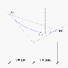
Circle; parameter is the distance between vertex and tangent point, see Fig. 1 – Circle - types 0 and 1.
Circle + radius
Circle; parameter is the radius of circle, see Fig. 1 – Circle - types 0 and 1. Radius and two tangents determine the circle. Length of tangents is calculated automatically.
Symmetrical parabola + tangent
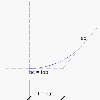
Parabola; parameter is the distance between vertex and tangent point (beginning or end of parabola), see Fig. 2 – Parabola – type 2. The length of tangent & axis of symmetry of parabola determine the parabola.
Parabola + tangent [begin]
Parabolic segment with the crown of parabola at the beginning of the curve; parameter is the distance between the beginning of the curve (tangent point at axis of symmetry of parabola) and the vertex of polygon that is considered, see Fig. 3 – Parabola – type 3.
Parabola + tangent [end]
Parabolic segment with the crown of parabola at the end of the curve. Parameter is the distance between the end of the curve (tangent point at axis of symmetry of parabola) and the vertex of polygon that is considered, see Fig. 4 – Parabola – type 4.
Parabola + vertical axis
Parabola with vertical axis with respect to macro co-ordinate system. Parameter is the length of projection of tangent into horizontal direction, see Fig. 5 – Parabola – type 5.
For the second input type, there is just one option
Group of points fitting
The points defined in the tables of co-ordinates are the points, which the curve of the tendon must fit. The parameters are the tangents of the curve at those points.
If you define the parameter equal to 100, then the tendon is oriented directly to the following point. If the parameter equals to –100, then the tendon is oriented back to the previous point. Therefore the pair of values 100 and –100 defines a straight part of the tendon between two points.
If the parameter equals to 1000, then the tangent is assumed unknown (arbitrary) and the program will calculate the tangent automatically.
As a result you can determine the limits -1.0 and +1.0 (angles 45°) for the parameters of reasonable tendon profile. For example the parameter equal 0.0 is the input for a horizontal tangent.
The principles of the algorithm is:
-
The user defined tangents are respected.
-
Three consecutive points with the identical y (z) co-ordinate will be fitted by a horizontal straight line.
-
The angles of tangent at anchors and at consecutive points are calculated (if they were not defined by the user). If possible, the whole first and last segment will be fitted by a straight line. If not, the straight line will be inserted into the half of the length of first and last segment.
-
If the distance of two consecutive points is significantly shorter than the distances of the other points, a straight line will be inserted into this segment.
-
The difference between radii of two consecutive curves is minimised.
-
The curved segment of opposite curvature is prohibited in connecting part between straight line and the curve.
-
If two tangents intersect in the half of the length of projection of the curve, a parabola with a vertical axis is applied.
-
In other cases two parabolas with vertical axis are applied.
Layout and controls of the Edit geometry dialogue
Note: The proportions of individual parts of the edit dialogue were deliberately distorted in order to fit the picture into one printed page.
Toolbar
Input table for XZ plane
Icon[Delete allnodes]
This command deletes all the nodes in the table for plane XZ.
Icon [Group of points fittings]
Switches the input mode – see paragraph Type of input above.
Input table
|
Coord X |
X-coordinate of the vertex of the source geometry. |
|
Coord Z |
Z-coordinate of the vertex of the source geometry. |
|
Curve type |
Type of curve "in" the vertex - see paragraph Type of input above. |
|
Curve parameter |
The parameter of the curve selected in the item above - see paragraph Type of input above. |
Graphical preview window
This graphical window shows the side-view the defined tendon shape.
You can use the combination "Press-and-hold keys Ctrl+Shift" + "Press-and-hold the mouse right button" and zoom-in or zoom-out the drawing, or the combination "Press-and-hold key Shift" + "Press-and-hold the mouse right button" and move the drawing around the graphical window of the dialogue.
Input table for XY plane
Icon [Delete all nodes]
This command deletes all the nodes in the table for plane XY.
Icon [Group of points fittings]
Switches the input mode – see paragraph Type of input above.
Input table
|
Coord X |
X-coordinate of the vertex of the source geometry. |
|
Coord Y |
Y-coordinate of the vertex of the source geometry. |
|
Curve type |
Type of curve "in" the vertex - see paragraph Type of input above. |
|
Curve parameter |
The parameter of the curve selected in the item above - see paragraph Type of input above. |
Graphical preview window
This graphical window shows the plan-view the defined tendon shape.
You can use the combination "Press-and-hold keys Ctrl+Shift" + "Press-and-hold the mouse right button" and zoom-in or zoom-out the drawing, or the combination "Press-and-hold key Shift" + "Press-and-hold the mouse right button" and move the drawing around the graphical window of the dialogue.
Main control buttons
The [OK] button confirms the input/changes made in the dialogue and closes it.
The [Cancel] button abandons the input/changes made in the dialogue and closes it.
Note: It is not allowed to input three successive points in one line. In other words, the direction of the tendon must change in each input vertex.


