Precise levelling method – cast-in-place
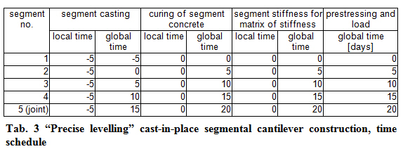
Also the modelling of “precise levelling” method in cast-in-place segmental cantilever construction method is quite simple. Let’s assume that segments are always stresses 5 days after casting. To simplify the matter, let’s assume that a five-day working cycle is used (transfer and rectification of casting carriage, casting, stressing). Individual construction stages are graphically identical to the “precise levelling” method for precast segmental cantilever construction and are shown in colour in Fig. 8. The time schedule of the step-by-step cast-in-place construction is presented in Table 3.
Dead load of segments is applied in the time of prestressing of the segments. Similarly to the dead load of closing joint, also the dead load of segments acts in fact in the time of casting. However, the appropriate segments do not yet exist in terms of stiffness in that time (neither in the model nor in the real structure) and are not capable of carrying any load. In the real structure, the load is transferred by the casting carriage to the previous segment as a point load. Considering the fact that a “young” concrete is subject to loads, the demand of an engineer to take account of “correct” time moments of dead load application is justified. This can be modelled by means of a set of point loads that will be input into the load case applied on the existing structure (the previous segment) in the time when a new segment is being cast. In the time of prestressing (and application of the dead load of the new segment) the set of point loads must be applied with the opposite sign in order to prevent doubling of the dead load. Also the load from the casting carriage can be additionally input to this set and in case of e.g. a bridge of a constant cross-section, both load sets (loading and unloading) can be moved along the structure together with the casting of a new segment. If also the effect of this load on creep of concrete should to be taken into account, the set of point loads must be defined in a permanent load case and not in a variable one.
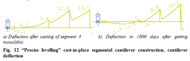
Once again, apparent breaks can be observed in deflection curves in Fig. 12. These breaks result from the fact that the deflection increments relate to the time of segment casting.