General Input
Composite beam - EN 1994-1-1
The tree item is capable either to check composite beam for a given geometry or directly design it according to EN 1994-1-1. The Design approach setting may be found within composite setup or composite member data.
It is intended to verify both non-fire ultimate limit and serviceability limit states for both construction and final stages all together. Based on inputted loading, check determines correct loading for each state and stage separately and runs a relevant set of partial checks for each type. The final result presented on the output is an envelope of maximum results of each partial check, each possibly coming from different section and combination key. Due to this, the result cannot be recognized as a section check, but as a member check, resulting in a uniform magnitude of the final unity check along the member. In addition to this, set of detailing checks together with stud layout is provided too.
User have the possibility to choose from 3 different outputs (Brief, Standard and Detailed) depending how much info is required.
The output may be in general split into several parts:
- Geometry data - providing info on span type and data related to the structure geometry
- Cross-section & materials - providing info on all relevant components such as steel section, concrete slab, steel sheeting, studs, ...
- ULS check of Construction stage - verifying set of ultimate limit state checks for construction stage
- SLS check of Construction stage - verifying set of serviceability limit state checks for construction stage
-
ULS check of Final stage - verifying set of ultimate limit state checks for final stage
- SLS check of Final stage - verifying set of serviceability limit state checks for final stage
- Detailing - providing info on detailing checks
- Moment Diagram and Stud layout - indicating how the studs may be placed based on the envelope moment diagram
In addition to the above an additional parts may be printed in the presence of opening:
- ULS check of Opening in Construction stage - verifying set of ultimate limit state checks for opening in construction stage
- ULS check of Opening in Final stage - verifying set of ultimate limit state checks for opening in final stage
If user has selected Check Design approach and if no loading is found for any of the check parts, the checks are skipped and a note is printed in that part. Design requires all types of loading to be present in order to be able to proceed with optimization.
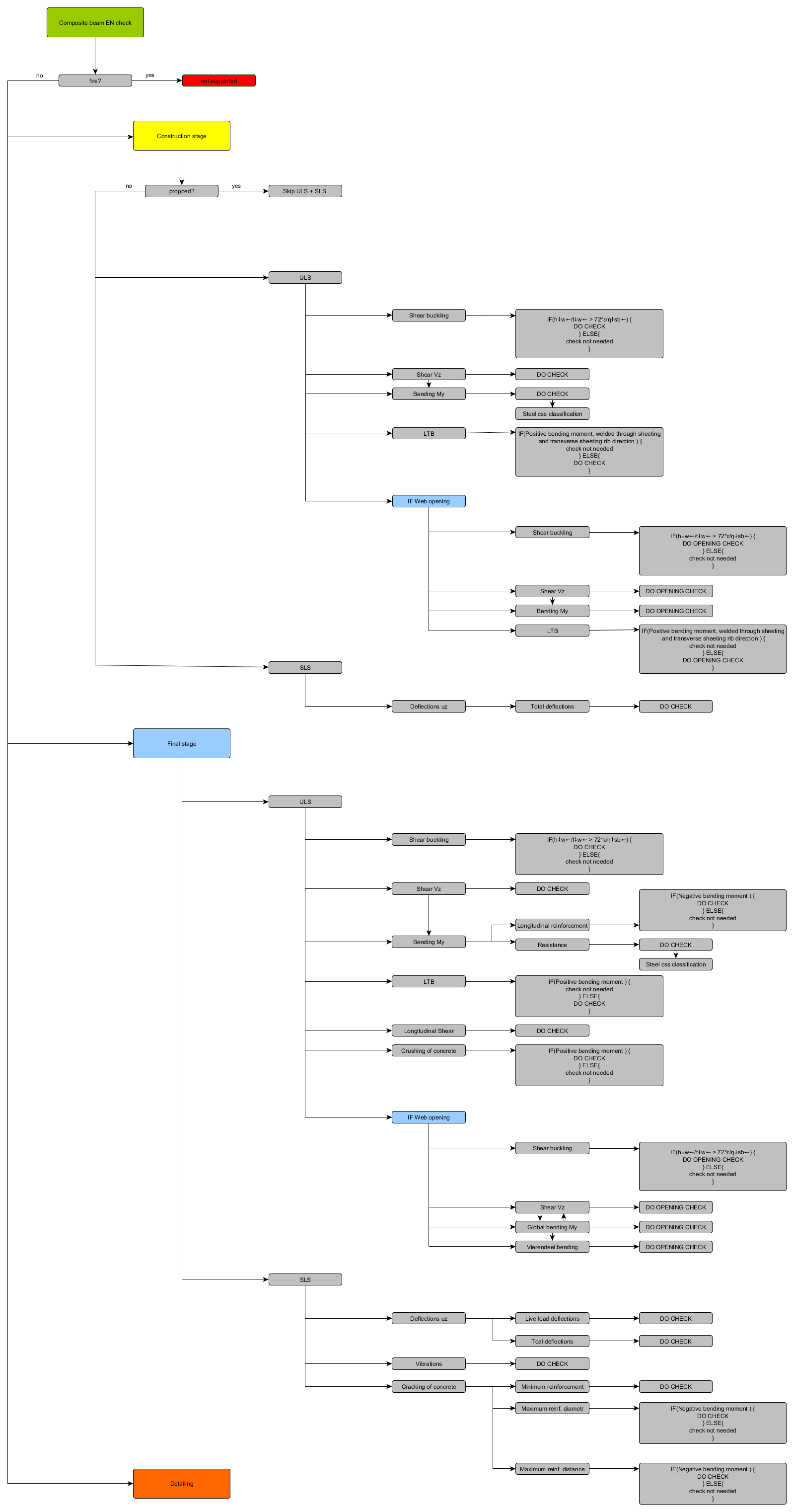
The routine is documented in the picture below:
Steel cross-section properties and Slab properties
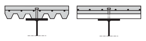
The checks are intended for non-encased composite beams which consist of steel section, profiled steel sheeting and a concrete slab.
There are several conditions which have to be fulfilled by the model, in order to be able to calculate the composite beam checks according to the EN 1994. If any of these conditions is not fulfilled, the calculation is terminated with unity check of 999 and a relevant error message displayed.
- The steel section has to be a rolled
- The analysis model has to be set to Standard.
- Type of connection has to be either: "With standard composite action" or "With advanced composite action". When using Type of connection “With advanced composite action”, normal forces are present in the composite beams which are however not considered in the composite checks.
- Shape of rib attribute has to be set to automatic in order to be able to calculate effective width according to EN 1994-1-1 and to get a correct span data. Manual input of effective width is however also supported.
- The direction of rib has to be either parallel or perpendicular to the steel section with a maximum tolerance of 10 degrees.
- Analysis model of the slab has to be set to Composite deck and it has to be made up from concrete. A valid profiled steel sheeting has to be defined.
It is recommended to define composite beam data on the checked beams to be able to change the properties of shear connectors, slab reinforcement and deflections independently for each beam. In such a case when the data are not defined the setup values are used. The only exception here is the reinforcement material, which is in this case linked to the steel material defined in the project data dialog and also the type of shear connector, which is taken as the 1st item in the library.
Please note, that for sheet welded cross-sections the weld size 'a' is taken into account only for the classification of the section. The weld size area is neglected in calculation of cross-section area.
Automatic generation of Result class and code combinations
In the load setup, the option for Generate composite combinations can be set YES to generate combinations or be set to NO to not generate combinations automatically.
If the option above is set to YES, an automatic generation (or update if they already exist) of EN combinations is run. Set B combinations for Ultimate limit state and Characteristic combinations for serviceable limit state are generated for each construction and final stage. Accidental combination for final stage is also generated. If any of the combination would be empty due to missing inputted load, such combination is not generated.
At the same time Composite design Result class is generated containing all generated combinations from above, except the accidental combination.
Design internal forces
Internal forces are taken from the verified section and may be checked in the Results service using the selected beam with the "Rib" option activated.