ULS final stage
Effective width calculation
Effective width used in the analysis model, for determination of internal forces, is calculated according to the EN 1994-1-1 Article 5.4.1.2. (4). This means that for the analysis model, the value of effective width is constant over the span of the beam.
Both variable effective width according to the EN 1994-1-1 and constant effective width may be used in the checks. This is determined by the property Shape of rib property separately for each member. Automatic Shape of rib will result in variable width calculation where adjacent members are detected to the maximum distance of the checked member length.
The variable effective width beff together with the distance Le (distance between points of zero bending moment in meters for typical continuous beams) is determined as given by EN 1994 -1-1 Article 5.4.1.2.
The position of the calculated section on the given span is determined based on the buckling system. If an internal y-y support is found and it is not located at the start or end of the member, such support is ignored. The warning "For a continuous beam, intermediate buckling supports y-y are ignored in both the analysis model and the check." is displayed.
Degree of shear connection
The connection between the structural steel section and the concrete slab is done through steel studs welded to the structural steel section. The present degree of shear connection must be greater than the minimum degree of shear connection. If this condition is not fulfilled, the calculation is terminated and an error is displayed.
Design resistance of shear stud
The design shear resistance of a headed stud, automatically welded in accordance with EN 14555, in a solid concrete slab is determined according to EN 1994-1-1 Article 6.6.3.1 (1). The influence of tension on the shear resistance described in EN 1994-1-1 Article 6.6.3.2 is assumed to be under the limit of 0,1*PRd and is thus neglected.
Design resistance of headed studs used with profiled steel sheeting is determined by EN 1994-1-1 Article 6.6.4.1 for sheeting with ribs parallel to the supporting beams and by EN 1994-1-1 Article 6.6.4.2 for sheeting with ribs transverse to the supporting beams.
Minimum degree of shear connection
User may choose whether for calculation of minimum degree of shear connection either standard EN or the rules given by publication “Minimum degree of shear connection rules for UK construction to Eurocode 4” by Couchman, G (2015) - SCI P405 should be used. Selection may be done in the composite setup and by default SCI P405 is used. The scope of the publication is limited to symmetric sections and application rules given by chapters 5.1 and 5.3.
SCI P405
The scope of the publication is limited to:
- Beams that are simply supported and internal (so the effective flange extends to either side of the beam).
- Beams not exceeding 22 m in span.
- Beams with solid webs, or with regularly spaced, large circular web openings
- Nominal deck profiles not exceeding 80 mm in height (to the ‘shoulder’ of the decking).
- Shear studs of 19 mm diameter with an embedment of at least 35 mm into the solid concrete above the (shoulder of) the decking profile, with a length after welding of not less than 95 mm.
- Studs that have mesh placed either at nominal cover (assumed to be clear of the head of the stud) or below the head of the studs (by at least 10 mm) – not to be tested and assumed to be fulfilled.
- Nominal total slab depth not exceeding 180 mm (depth of concrete over the decking not exceeding 100 mm).
- Studs with a maximum longitudinal spacing as defined in Section 7 of this publication.
User may select a starting set of application rules to be used. In case selected application rules cannot be applied, respective warning message is displayed.
Decision diagram of the routine may be seen on the picture below:
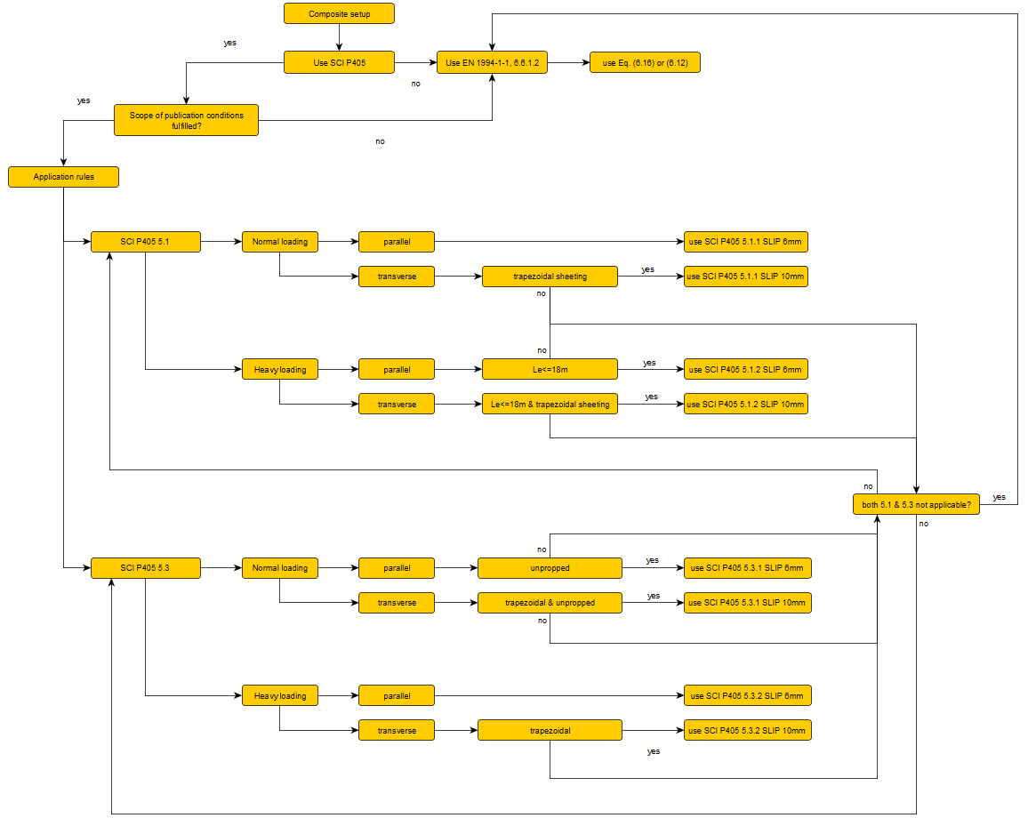
The loading is assumed to be "Normal" unless the design moment due to factored imposed (variable) load exceeds 70% of the total moment. Then the loading is recognized as "Heavy".
When decking is parallel to the beam, the studs may be assumed to achieve 6 mm slip capacity. When decking is transverse to the beam, the studs may be assumed to achieve 10 mm slip capacity.
The minimum degree of connection rules, which concern limiting the slip at the concrete-steel interface, must be applied in conjunction with the detailing rules given in Section 7 of the publication for maximum longitudinal shear connector spacing. The maximum spacing should not be greater than 450 mm. With transverse decking this equates to a need to have a stud in every trough.
Formulas given by the publication:
Chapter 5.1.1 (Normal loading) - slip capacity limited to 6 mm (parallel direction of ribs):

Chapter 5.1.1 (Normal loading) - slip capacity limited to 10 mm (transverse direction of ribs):

Chapter 5.1.2 (Heavy loading) - slip capacity limited to 6 mm (parallel direction of ribs):

Chapter 5.1.2 (Heavy loading) - slip capacity limited to 10 mm (transverse direction of ribs):

Chapter 5.3.1 (Normal loading) - slip capacity limited to 6 mm (parallel direction of ribs):

Chapter 5.3.1 (Normal loading) - slip capacity limited to 10 mm (transverse direction of ribs):

Chapter 5.3.2 (Heavy loading) - slip capacity limited to 6 mm (parallel direction of ribs):

Chapter 5.3.2 (Heavy loading) - slip capacity limited to 10 mm (transverse direction of ribs):

Standard EN
The minimum shear connection for steel sections with equal flanges is determined according to EN 1994-1-1 Article 6.6.1.2.
If the conditions given by EN 1994-1-1 Article 6.6.1.2 (3) are satisfied, an alternative method for the calculation of the minimum degree of shear connection, according to the same article, may be used. This method is used by default.
Degree of shear connection present
The shear connection η available in the section is calculated based on resistances and the equation given by the EN 1994-1-1 Article 6.6.1.2 (1):

with:
Nc - total resistance of the shear studs within the distance Le/2 given as:

PRd - the resistance of one steel stud, taking into account the presence of steel sheeting
nsp - number of shear studs available within a distance Le/2, rounded down if necessary
- for parallel direction:

- for transverse direction:

Le - distance between points of zero bending moment
ls - distance between the shear studs in the direction of the beam
nr - number of studs in a single row
nrib - number of available ribs within the distance Le
trough - parameter taking into account placement of the studs in ribs of steel sheeting
(each rib - 1, every 2nd rib - 2, every 3rd rib - 3)
Nc,f - minimum resistance of currently active components
- for positive bending moment:

- for negative bending moment:

Npl,a - plastic resistance of the steel section
Nc,Rd - compression resistance of the concrete flange
Fs - tension resistance of the reinforcement provided within the effective width
Shear buckling
According to EN 1994-1-1 Article 6.2.2.3, the shear buckling of the section should be checked as defined in the EN 1993-1-5 Article 5. If the defined ratio hw/tw is greater than the given limit, the contribution of the web is calculated, assuming that end post are non-rigid, together with contribution of the flanges and resulting value is compared to the given limit. If the design shear force VEd is greater than the given resistance Vb,Rd, the status of this check is set to "Not OK" and the warning that "The shear buckling resistance of the section is not adequate." is displayed.
Vertical shear
According to EN 1994-1-1 Article 6.2.2.2, the resistance to vertical shear of the section should be taken as the resistance of the structural steel section calculated by EN 1993-1-1 Article 6.2.6.
If the design shear force VEd is greater than the given resistance Vpl,Rd, the status of this check is set to "Not OK" and the warning that "The shear resistance of the section is not adequate." is displayed.
Bending moment
Influence of shear
As given by EN 1994-1-1 Article 6.2.2.4, if the vertical design shear force VEd exceeds half the shear resistance Vpl,Rd, the reduced design steel strength fyb should be used for calculation of the bending moment resistance . This reduction is given by EN 1994-1-1 Article 6.2.2.4 (2). If the calculated value ρ is bigger than 1, the calculation is terminated and the final unity check is set to 999.
In the final stage, the reduced value of the design yield strength (1-ρ)*fyb is used only for web of the steel cross-section.
Longitudinal reinforcement
A minimum amount of reinforcement defined by the EN 1994-1-1 Article 5.5.1 (5) has to be fulfilled. If the requirement is not fulfilled, a warning is displayed and the appropriate unity check is set to "Not OK".
Resistance
The plastic bending moment resistance Mpl,Rd is calculated according to EN 1993-1-1 Article 6.2.1. Any resistances of the ribbed part of the concrete and the steel sheeting are neglected. As given in EN 1994-1-1 Article 6.2.1.1 (4), the tensile resistance of full concrete part is also neglected.
The plastic moment resistance for cross-sections with full degree of shear connection (η = 1) is calculated according to EN 1994-1-1 Article 6.2.1.2. If the conditions defined by EN 1994-1-1 Article 6.2.1.2(2) are fulfilled, the reduction factor β is used for determination of the final bending moment resistance MRd. When the defined ratio xpl/h is greater than 0.4, the design is terminated and an error is displayed.
The plastic moment resistance for cross-sections with partial degree of shear connection (ηmin ≤ = η < 1) is calculated according to EN 1994-1-1 Article 6.2.1.3. The final bending moment resistance MRd is calculated according to equation 6.1 given by EN 1994-1-1 Article 6.2.1.3(5), however the user also has the possibility to use the plastic theory calculation method given by EN 1994-1-1 Article 6.2.1.3(3), where the reduced value of Ncf is used in the calculation. In this case the final bending moment resistance MRd is taken as Mpl,Rd directly obtained from the calculation. The usage of the plastic method can be activated in the member data dialog of the check.
If the design bending moment MEd is greater than the given resistance MRd, the status of this check is set to "Not OK" and the warning that " The bending moment resistance of the section is not adequate." is displayed.
Classification of the cross-section
According to the EN 1994-1-1 Article 5.5, the cross-section should be classified according to EN 1993-1-1 Article 5.5, Table 5.2.
Only cross-sections classified as class 1 or class 2 are supported by the checks. If the cross-section is classified differently, a warning is displayed.
Resistance calculation routine may be seen on the picture below:

Lateral torsional buckling
For the lateral torsional buckling check, the reduction factor χLT is calculated by the general case given in EN 1993-1-1 Article 6.3.2.2. The relative slenderness λLT,rel is calculated according to the simplified method given by the Designers’ guide to EN 1994-1-1, Article 6.4.3, (D6.14).

with:
tw - thickness of the web of the steel section
hs - distance between the centers of the flanges of the steel section
tf - thickness of the flange of the steel section
bf - width of the flange of the steel section
fy - yield strength of the steel section material
Ea - E modulus of the steel section material
C4 - user input of load factor given by the Designers’ guide to EN 1994-1-1, Appendix A
The reference verifies whether the cross-section meets the criteria for usage of this simplified method. The calculated value F, given by the equation (D6.15),

is being compared with the limit value Flim, defined by Appendix A, Table A.2 of the reference.
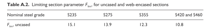
If the Flim is greater than the calculated value F, a warning is displayed.
The LTB check is being performed when the design bending moment is negative; else it is assumed that a continuous restraint to the compression flange of the steel beam is provided by the shear studs, thus the beam is not susceptible to lateral torsional buckling.
If the design bending moment MEd is greater than the given resistance Mb,Rd, the status of this check is set to "Not OK" and the warning that "The later torsional buckling resistance of the section is not adequate." is displayed.
Longitudinal shear
Longitudinal shear is checked according to the EN 1994-1-1 Article 6.6.6. The contribution of the steel sheeting is neglected in this case.
The Designers’ guide to EN 1994-1-1 Article 6.6.6 mentions the content of the EN 1994-1-1 Article 6.6.6.1(4) which indicates that the design longitudinal shear for the concrete slab should be "consistent with the design and spacing of the shear connectors". This implies that the resistance of the shear connection, rather than the design loading, determines the longitudinal shear. This approach is used for determination of the design shear flow:

with:
nr - number of studs in a single row
PRd - the resistance of one steel stud, taking into account the presence of steel sheeting
n - number of shear planes (both sides are evaluated separately and are considered if effective width of the side is larger than MIN(Le/8, 4*hs)
hs - total height of the composite slab (including sheeting)
ls - distance between the shear studs in the direction of the beam
hf - height of full concrete
Using formula 6.25 given by EN 1994-1-1 Article 6.6.6.4 (4), the minimum amount of longitudinal shear reinforcement is calculated and compared with the provided reinforcement. The angle of the concrete strut may be defined in the member data dialog and has to be within the limits for compressed flanges as defined by EN 1992-1-1 Article 6.2.4 (4). A value of 26.5° is used by default.
If the required reinforcement At is greater than the provided reinforcement At,prov, the status of this check is set to "Not OK" and the warning that " The longitudinal shear reinforcement of the section is not adequate." is displayed.
Crushing of the concrete flange
To prevent crushing of the compression struts in the flange, the condition given by the EN 1992-1-1 Article 6.2.4 (4) should be satisfied. The angle of the concrete strut may be defined in the member data dialog and has to be within the limits for compressed flanges as defined by the article. A value of 26.5° is used by default.
If the formula 6.22 given by the reference is not fulfilled, the status of this check is set to "Not OK" and the warning that " The crushing resistance of the concrete is not adequate." is displayed.
The check of crushing of the concrete flange is performed only in case of positive bending, i.e. when the concrete gets compressed.