ULS final stage - unstiffened openings
In Scia Engineer it is possible to verify the resistance of a circular
To verify the resistance of the composite beam with isolated web opening these failure modes need to be verified for construction stage:
- Shear buckling next to the opening
- Vertical shear at the centre of the opening
- Global bending verified at the centre of the opening
- Lateral torsional buckling at the centre of the opening
The results of these checks are presented by an additional unity checks in separate part of the output
Design internal forces for an opening are interpolated for the middle section of the opening. Maximum values of the forces are used independently on its combination key.
The opening
In order to qualify an opening for the design it has to pass the conditions below in the given order:
- check box for "Used for analysis and design" has to be activated
- the shape of the opening is not set to "Cross-section"
- the opening does not interfere with beam flanges in vertical direction
- the opening is not breaching the member in longitudinal direction
- opening Alpha and Beta rotations are set to zero and opening orientation is set to Y
- the opening does not interfere with other opening
If the opening does interfere with beam flanges in vertical direction, an error will be displayed and unity check will be set to 999. If any of the remaining conditions above is not fulfilled respective warning is displayed and opening will not be used for the design.
In case of multiple openings are qualified for the design, user may choose to see results of all openings or only the extreme one, by using "Openings and web posts" in Output setting properties.
Opening shape
Currently it is possible to input either rectangular
For circular openings:


For elongated openings:


Effective width
Effective width of slab at an opening for a simply supported span with a sufficient available width of slab on both sides and ignoring b0, at a distance x from the nearest support, is given as:
For x ≤Le/4 as:

For x > Le/4 as:

Final effective with accounting for the available space on the sides of the beam either to the edge of the slab or to the middle of the perpendicular span:

with:
bl - available space to the left of the beam
br - available space to the right of the beam
Shear buckling
According to EN 1994-1-1 Article 6.2.2.3, the shear buckling of the section should be checked as defined in the EN 1993-1-5 Article 5. If the defined ratio hw/tw is greater than the given limit (web is classified as slender), the contribution of the web is calculated, assuming that end post are non-rigid, together with contribution of the flanges and resulting value is compared to the given limit .
For slenderwebs with isolated openings, the contribution of shear buckling resistance of a web may be modified to take account of an isolated opening. The shear buckling resistance of the slender web with isolated openings may be taken conservatively as:

with:
Vbw,o,Rd - shear buckling resistance of an unperforated web
ho - height of opening
lo - length of opening (For a circular opening, lo= ho in this formula)
hw - clear depth between flanges
If the design shear force VEd is greater than the given resistance Vb,Rd, the status of this check is set to "Not OK" and the warning that "The shear buckling resistance of the section is not adequate." is displayed.
Vertical shear
Steel section
The vertical shear resistance of the perforated steel section is taken as sum of the top and bottom Tee resistances. The resistance of Tee section is calculated by the general formula given by EN 1993-1-1 Article 6.2.6:

with:
fyb - yield strength of the material
γM,0 - partial safety factor for steel under fire conditions
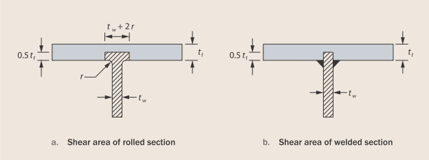
Av - section shear area calculated as:
for rolled sections:

for welded sections:

Av,t,T - shear area of top Tee
Av,b,T - shear area of bottom Tee
Shear area of Tees of rolled and welded sections:
Full dimensions of opening are used in calculation of vertical shear resistance compared to global and Vierendeel bending.
Concrete slab
EN 1994-1-1, §6.2.2.2(1) allows the final design plastic shear resistance of a composite cross-section to include a contribution from the concrete slab. The choice may be done in the composite setup by activating "Use concrete for shear resistance" check box.
For reinforced concrete members without shear reinforcement, EN 1992-1-1, §6.2.2 gives the design shear resistance as:

with minimum:

with:

 (hc in mm)


Nc,Ed - design force in concrete calculated in global bending . (If NbT,Ed < Nc,Rd: Nc,Ed= NbT,Rd. If not, Nc,Ed= Nc,Rd.)
fck - characteristic resistance of concrete in compression
beff,o - effective width of the composite beam at opening
Asl - area of tensile reinforcement in longitudinal direction
bw - effective width of concrete flange for shear ( = bf+2*hs,eff)
hc - effective height of the slab (full concrete height)
hs,eff - effective slab height for punching shear ( = 0.75*hs)
hs - total height of composite slab
If the design shear force VEd is greater than the given resistance Vpl,Rd, the status of this check is set to "Not OK" and the warning that "The shear resistance of the section is not adequate." is displayed.
Global bending
Influence of shear
As given by EN 1994-1-1 Article 6.2.2.4, if the vertical design shear force VEd exceeds half the shear resistance Vpl,Rd, the reduced design steel strength fyb should be used for calculation of the bending moment resistance . This reduction is given by EN 1994-1-1 Article 6.2.2.4 (2) and as given by the SCI reference, is used for opening only when ρ>0.5. If the calculated value ρ is bigger than 1, the calculation is terminated and the final unity check is set to 999.
The reduced value of the design yield strength (1-ρ)*fyb is used for the whole Tee section resistance.
Resistance
In order to use the given plastic theory, steel sections should be classified as Class 1 and 2 in accordance with EN 1993-1-1 [6]. The cross-section classification correctness will be ensured by introducing the limit of 10*tw*ε limit for height of compression Tee (which will be checked in case Plastic neutral axis lies in the steel section only).
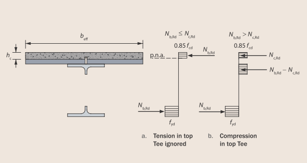
To determine the plastic bending resistance at the centreline of the opening, the forces in the Tees and the slab must be in equilibrium. Two situations are possible: with the plastic neutral axis in the slab and with the plastic neutral axis in the top Tee.
The possible cases of plastic stress blocks in a perforated composite beam:
Resistance of concrete slab including the resistance of shear studs is given as:

with:
fcd - design resistance of concrete in compression ( = fck/γc)
beff,o - effective width of the composite beam at opening
nsc - number of shear connectors placed over the distance from the nearer support to the centreline of the opening
PRd - design resistance of the shear connectors used with profiled sheeting
Resistance of bottom Tee in tension is given as:

with:
AbT - cross-sectional area of bottom Tee
Case 1: Nc,Rd ≥ NbT,Rd
The compression resistance of the full thickness of the slab at the position of the opening is the lesser of the compression resistance of the effective width of slab and the resistance provided by the shear connectors between the end of the beam and the centreline of the opening. In this case plastic neutral axis is in the concrete slab.
The plastic bending resistance is then given by:

with:
heff - effective depth of the beam between the centroids of the Tees
zt - depth of the centroid of the top Tee from the outer edge of the top flange
zc - depth of concrete in compression

The axial force in bottom Tee is calculated as:

with:
MEd - design bending moment at opening
Case 2: Nc,Rd < NbT,Rd
In this case, the compression resistance of the full depth of the effective width of slab is less than the tension resistance of the bottom Tee and equilibrium is achieved by developing compression in the top Tee. For this situation, it is conservative to assume that the top Tee is uniformly stressed and subject to a force equal to the difference between the tension resistance of the bottom Tee and the compression resistance of the slab, i.e. it provides a resistance equal to NbT,Rd − Nc,Rd. In this case plastic neutral axis is in steel Top tee.
The compression resistance of unstiffened top Tee is limited by cross-section class 2 limit, thus:

with:

AtT - cross-sectional area of compressed top Tee for global bending
hwt - height of the web out stand of a top Tee

hw - clear distance between flanges of unperforated section
ho - height of opening
eo - eccentricity of opening
The plastic bending resistance is then given by:

with:
zc - depth of concrete in compression ( = hc)
To determine the axial force in the bottom Tee for this case, expression from Case 1 should be used unless this gives NbT,Ed > Nc,Rd. In such case the force may be taken as:

As given by SCI P355 Article 3.2.4, for the composite design of beams with large openings close to the supports, it is likely that a shear connection resistance equal to 40% of the tensile force developed in the bottom Tee (i.e. Nc,Rd ≥ 0.4*NbT,Ed) will be required to ensure adequate composite bending resistance. If this is not achieved by the application of current minimum degree of shear connection rules, then additional shear connectors should be provided for critical parts of the span or composite action should be neglected when calculating the global bending resistance at opening locations with an inadequate number of shear connectors.
In such a case the contribution of concrete is neglected in the calculation of bending resistance:

To determine the axial force in the bottom Tee for this case only steel section is used:

If the design bending moment MEd is greater than the given resistance Mo,Rd, the status of this check is set to "Not OK" and the warning that " The bending moment resistance of the section is not adequate." is displayed.
Vierendeel bending
Bending resistance of Tee
Classification of a Tee
The out stand of the web of the Tee may be classified depending on the effective length of Tee lo,eff and the out stand depth ht or hb, as given by the reference. For this local buckling classification, the effective length of the opening is defined conservatively:
For rectangular opening as:

For circular opening as:

For elongated openings as:

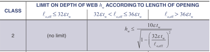
The web of top and bottom Tee is limited according to the table below to ensure the classification of Tee fulfils the limit of Class 2.
Influence of shear
The effect of the high shear forces in the Tees is to reduce the effectiveness of the web. However, the reduction of the web thickness for high shear influences the Vierendeel bending resistance of the Tees and in turn the distribution of shear. For the calculation of the resistance it is assumed each Tee takes the same part of the vertical shear.

with:
VEd - design shear force at the opening
Vc,Rd - shear resistance of concrete (if used for shear resistance)
Vt,Rd - shear resistance of top Tee
Vb,Rd - shear resistance of bottom Tee
No reduction in web thickness is required for µ≤ 0.5, but if the value is larger than that, effective thickness of the web for Vierendeel bending is calculated as:

The resulting value of tw,eff is applied to the calculation on moment resistance for both tees.
Resistance
Vierendeel bending is the means by which shear force is transferred across a large opening. The sum of the Vierendeel bending resistances at the four corners of the opening, plus the contribution due to composite action between the top Tee and the slab, must therefore not be less than the design value of the difference in bending moment from one side of the opening to the other due to that shear force; this may be expressed as:

with:
MbT,NV,Rd - bending resistance of the bottom Tee, reduced for coexisting axial tension and shear
MtT,NV,Rd - bending resistance of the top Tee, reduced for coexisting axial tension and shear
Mvc,Rd - local composite Vierendeel bending resistance
VEd - design value of the vertical shear force (taken as the value at the lower moment side of the opening)
le - effective length of the opening for Vierendeel bending
The plastic bending resistance of a top or bottom Tee section in the absence of axial force (including possible reduction due to vertical shear) is given by the following expression, assuming that the plastic neutral axis is in the flange of the Tee:

with:
Aw,T - cross sectional area of web of the respective Tee ( = hw,T*tw)
hw,T - depth of web of the respective Tee
Af - cross sectional area of the flange
tf - thickness of the steel flange
bf - width of the steel flange
zpl - distance between the plastic neutral axis in the flange and top of the flange

Similar formula assuming that the plastic neutral axis is in the web of the Tee:

with:
zpl - distance between the plastic neutral axis in the web and bottom of the flange

Influence of normal force
The reduction of plastic bending resistance for co-existent axial force may be determined according to the following approximate formula:

with:
Mpl,V,Rd - bending moment resistance of a Tee including possible reduction from vertical shear
Mpl,NV,Rd - bending moment resistance of a Tee including possible reduction from vertical shear and axial force
Npl,Rd - axial resistance of the Tee
NEd - design value of the axial force in the Tee due to the global bending action, either the compression force in the top Tee or the tension force in the bottom Tee.
Top Tee:
For Case 1 NEd= 0 and for Case 2: NEd= max(NbT,Rd - Nc,Rd).
Bottom Tee:
NEd= NbT,Rd
Local composite resistance
A contribution to the Vierendeel bending resistance occurs due to local composite action of the top Tee with the slab.The bending resistance due to composite action of the top Tee with the slab is given
conservatively by:

with:
ΔNc,Rd -compression force developed by the shear connectors placed over the opening (= nsc,o*PRd)
nsc,o - number of shear connectors placed over the opening
PRd - design resistance of the shear connectors used with profiled sheeting
zt - depth of the centroid of the top Tee from the outer edge of the flange (as an approximate = tf)
ko - reduction factor due to the flexibility of the opening, which takes account of second order effects together with the combination of shear and tension forces at the edge of the opening, generally given as below, but take as 1.0 if lo ≤5*hwt

lo - length of opening
hwt - depth of the top Tee
If the design effect of Vierendeel bending is greater than the given resistance, the status of this check is set to "Not OK" and the warning that " The bending moment resistance of the section is not adequate." is displayed.