Averaging strip
For general description of this functionality see Averaging_strips chapter.
The averaging algorithm can be applied to (i) internal forces in slabs and (ii) required reinforcement areas in slabs. Averaged internal forces are calculated from non-averaged internal forces and averaged required reinforcement areas are calculated using these averaged internal forces.
To create a new averaging strip the user may simply double click item Averaging strip in Concrete Advanced tree. The dialogue shown below appears. The user may define in it a few parameters which will determine the averaging strip location and its parameters. After confirmation the user defines averaging strip location in the graphical window. For detailed description see Defining a new averaging strip chapter.
Example
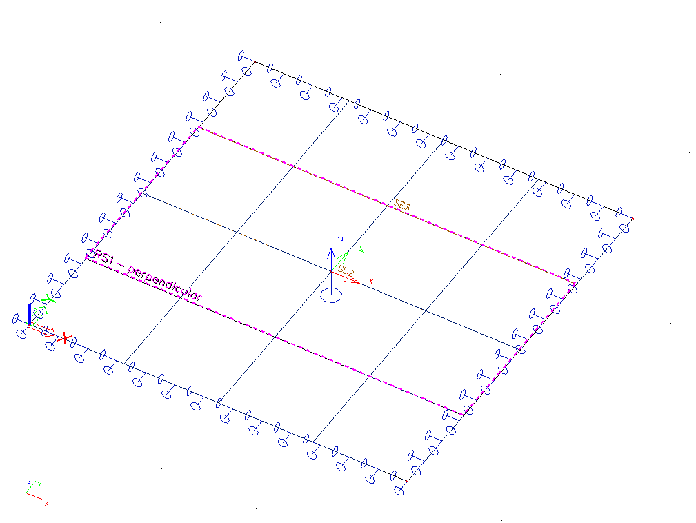
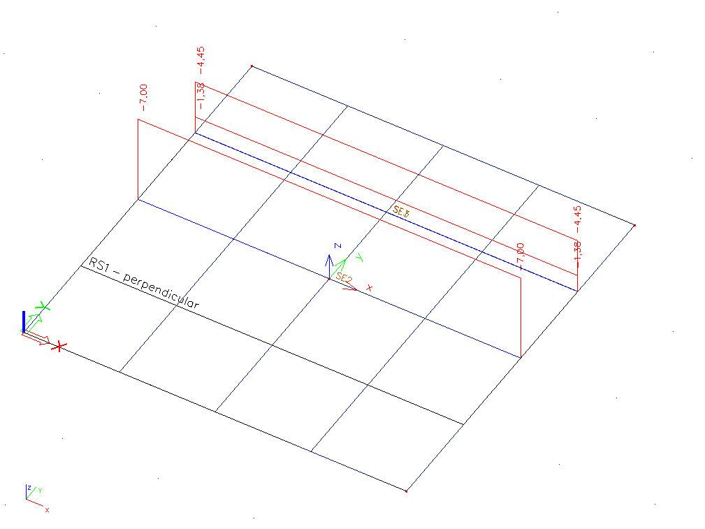
We can demonstrate the functionality on a simple example. Let’s create a 4x4 meters concrete slab with thickness of 200 mm, made of concrete C20/25. It will be supported according to the picture and subject to self weight. The mesh size is set to 1 meter. Two meter wide averaging strip was input in the Y direction with the averaging direction set to 'Perpendicular'.
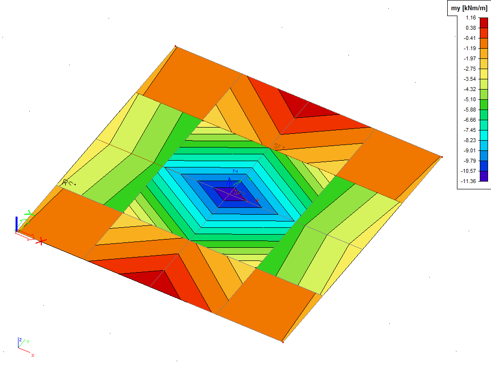
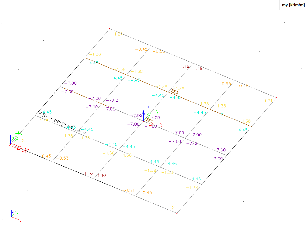
Non-averaged result of moment my with location parameter set to In nodes, no avg.
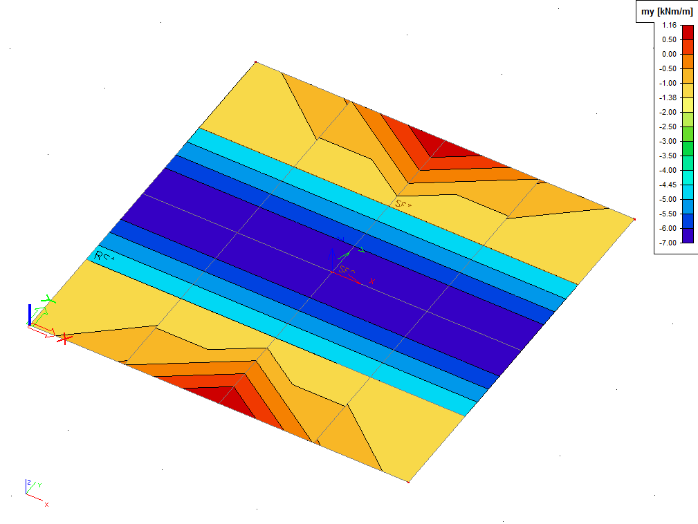
Results of moment my averaged with averaging strip, with location parameter set to In nodes, no avg.
Manual verification
Create sections perpendicular to the inputted averaging direction. In this example, the averaging was set to 'perpendicular' => create sections in longitudinal direction.
- 2D section A is input just outside the strip from (0;3,001) to (4;3,001)
- 2D section B is input just inside the strip from (0;2,999) to (4;2,999)
- 2D section C is input in the middle of the slab from (0; 2) to (4;2)
Non averaged result of moment my on 2D sections with location parameter set to In nodes, no avg. Parameter course is set to Precise possibility.
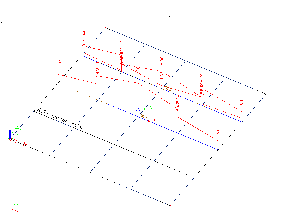
Non averaged result of moment my on 2D sections with location parameter set to In nodes, no avg. Parameter course changed to Uniform possibility.
The conclusion is that in 2D section A the moment my has value -1,38 KNm, in 2D section B -4,45 KNm and in 2D section C -7 KNm.
Numerical results of moment my averaged with averaging strip, with location parameter set to In nodes, no avg.
Conclusion
Now if we compare this averaged numerical results in mesh nodes and the non averaged results on 2D sections, we come to the conclusion that the values are equal.
Basic size of the averaging strip should be, in general, sum of the width of the support and thickness of the slab doubled. Nevertheless, the final size of the averaging strip should be always checked by an experienced engineer.
If the averaging strip is not in the coordinate system of the macro, then the transformation of internal forces to the averaging strip LCS is done before the averaging itself. After that, a backward transformation of the averaged internal forces back to the macro coordinates is performed.
A special view parameter can be found in the View parameters setting dialogue, under folder Structure/Averaging strips. Tick option Display to see the averaging strips (default) or clear the option to hide them.