Model
Structure
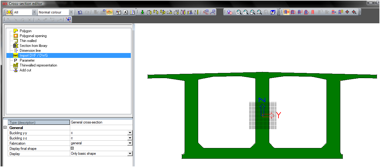
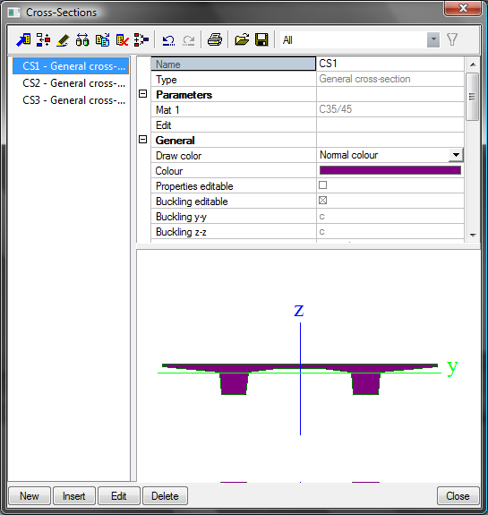
Cross-sections
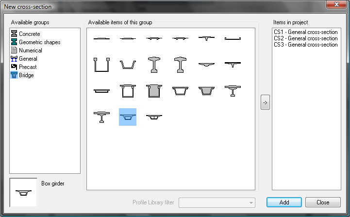
The structure is defined by standard modelling using in SCIA Engineer (SEN). The cross-sections are defined in CSS library using button New. There are several predefined Precast and Bridge CSS.
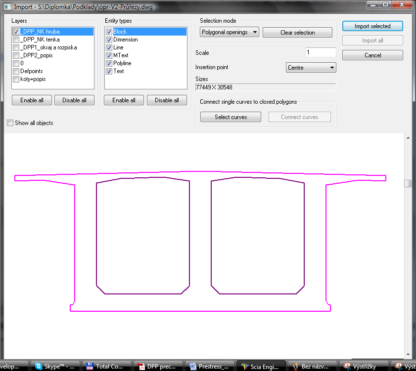
The General CSS enables to user prepares completely different CSS himself. It is possible to define it using definition of polygons directly in SEN or import CSS from dwg or dxf format.
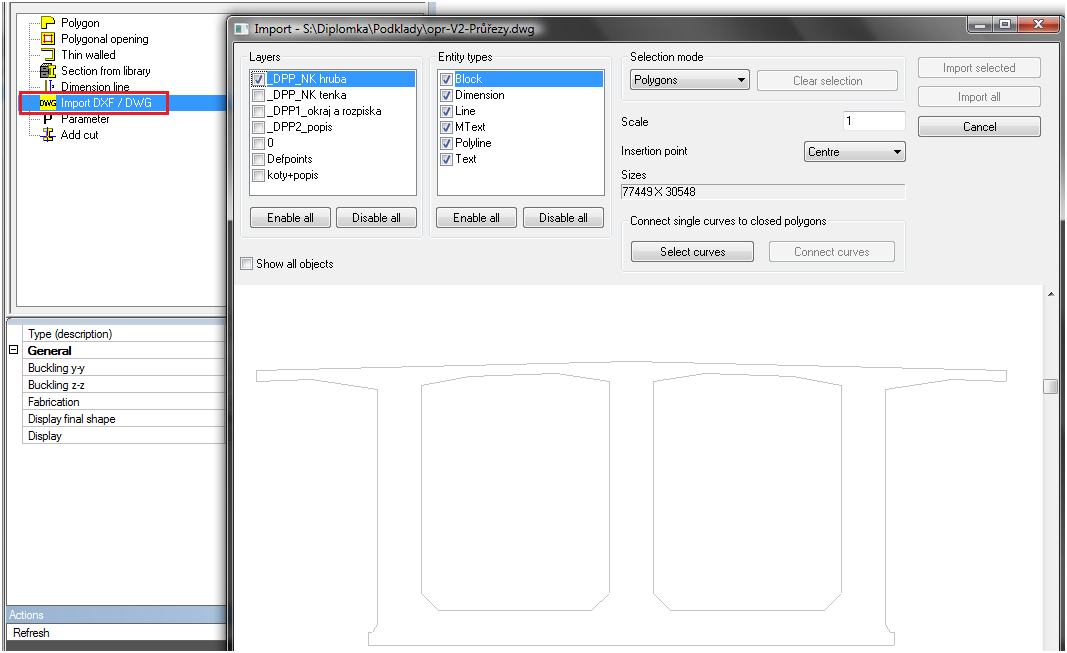
The CSS in the drawing format has to be prepared by Lines and Polylines. Connect all polylines is necessary to do as first (Select curves>Connect curves). Then polylines are created.
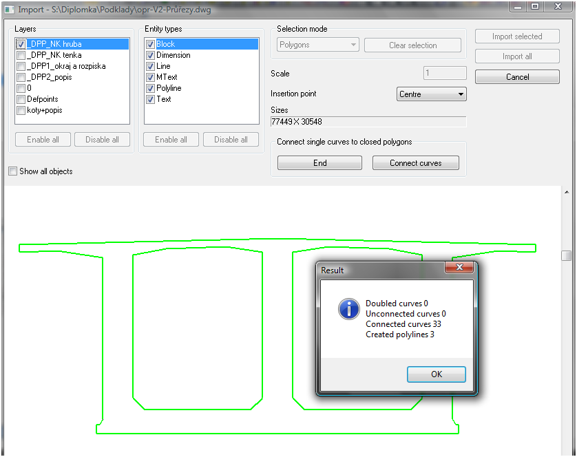
The selection of polygons and polygons openings is necessary for proper import from drawing format. User selects Selection mode>Polygons and selects outer polyline. Then he switches to Polygons openings and selects the polylines representing the openings. Afterthat the CSS can be imported from drawing format to SEN as general CSS
The cross-sections (CSS) should be also imported from previous similar SEN project.
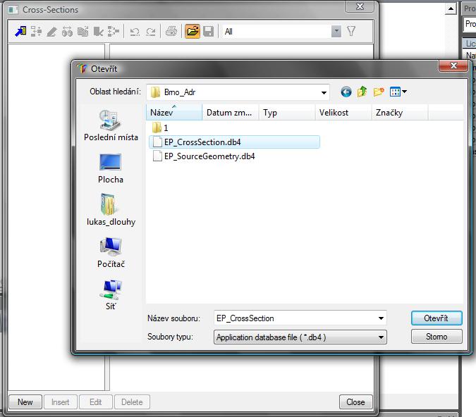
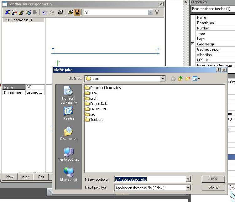
The user can select which CSS will be import from user database file.
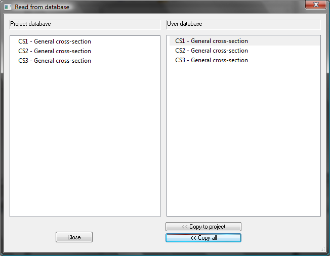
The dialog of CSS looks like following
Beams
The beams are defined using item Structure>1D Member>Beam with following properties.
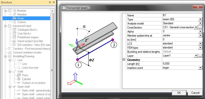
The following lengths of the beams will be defined in meters and appropriate CSS will be selected.
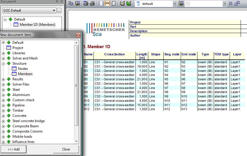
|
B1 |
1,0 |
|
B2 |
19,0 |
|
B3 |
1,0 |
|
B4 |
4,0 |
|
B5 |
21,0 |
|
B6 |
1,0 |
|
B7 |
4,0 |
|
B8 |
21,0 |
|
B9 |
1,0 |
|
B10 |
4,0 |
|
B11 |
15,0 |
|
B12 |
1,0 |
The user can see table of the beams in Document>Structure>Members
The coordinates of the beam´s nodes are possible to modify by Table edit geometry.
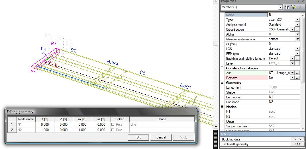
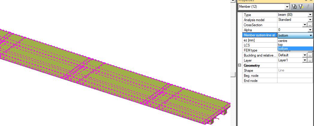
The alignment of the CSS should be changed to the bottom using filter of the beam in ones step because of different CSS in the structure.
Supports
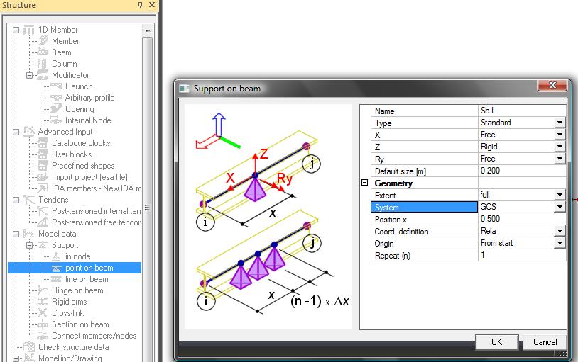
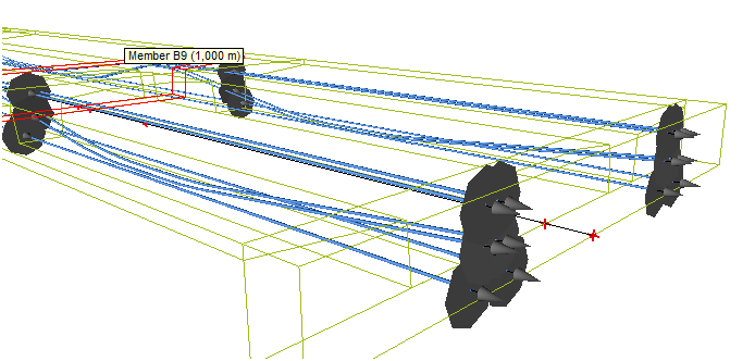
The supports should be defined using Structure > Model data>Support>Point on beam. The Z support is defined on support in the middle of the beam B1, B3, B9 and B12. The X, Z support is defined in the middle of the beam B6.
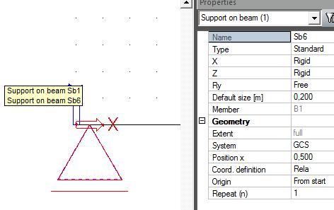
The additional support in the first beam has to be defined twice, because it is different during the construction stages.
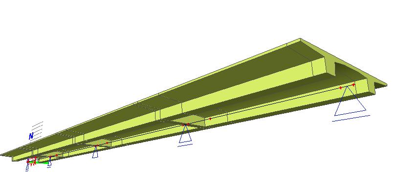
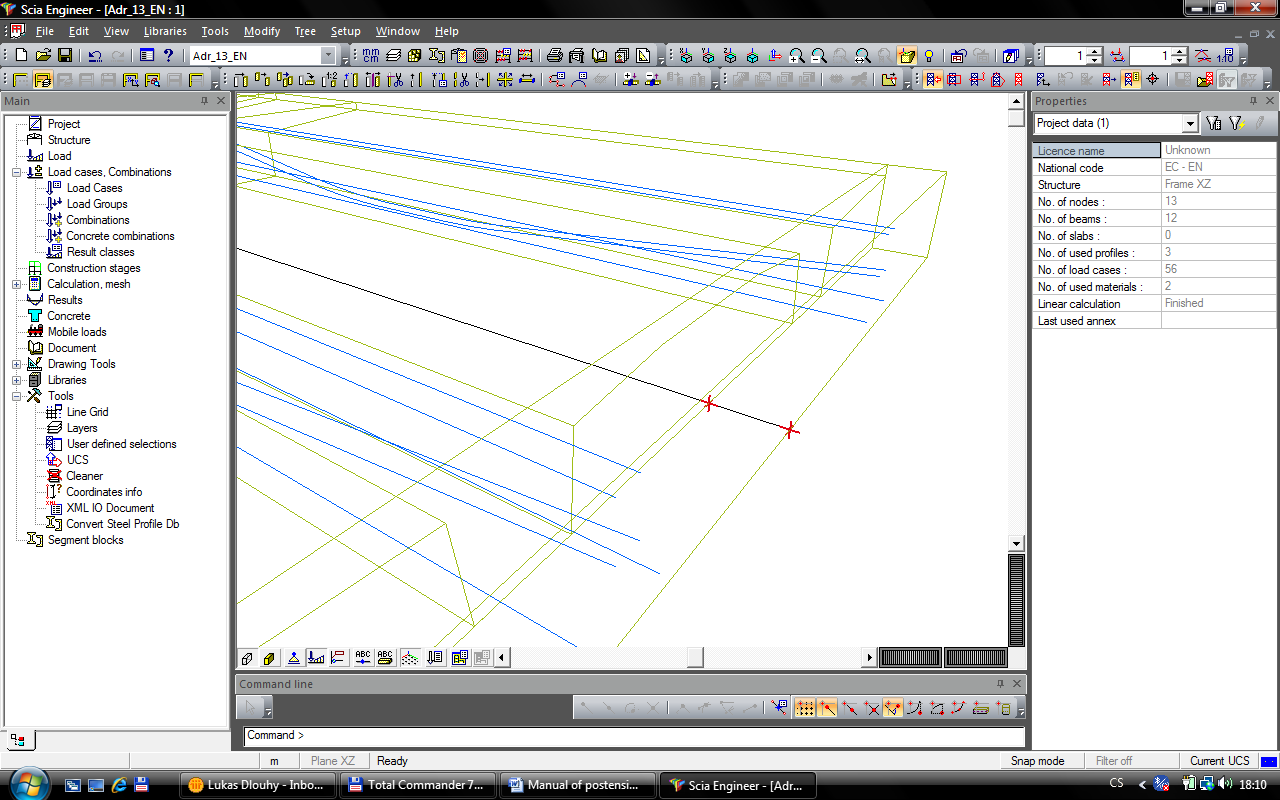
The 3D perspective model of the structure looks like following.
Prestressing
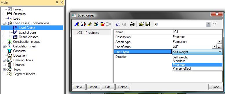
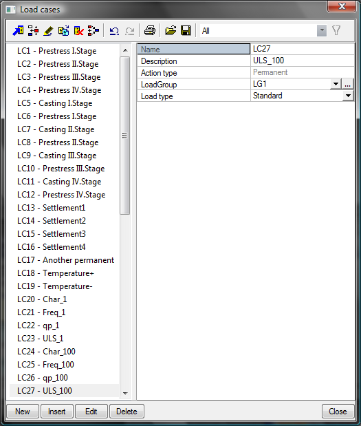
The loadcase type Prestress has to be defined for definition of the postensioned tendons. The loadcase is defined using Load cases, Combinations > Load cases.
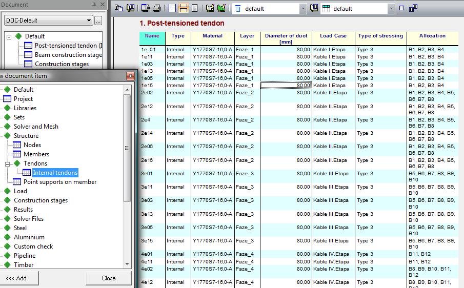
The postensioned tendons are possible to defined now in Structure>Tendons>Internal postensioned tendons. There are many input values and the most important is explained. The following items will be defined in this example.
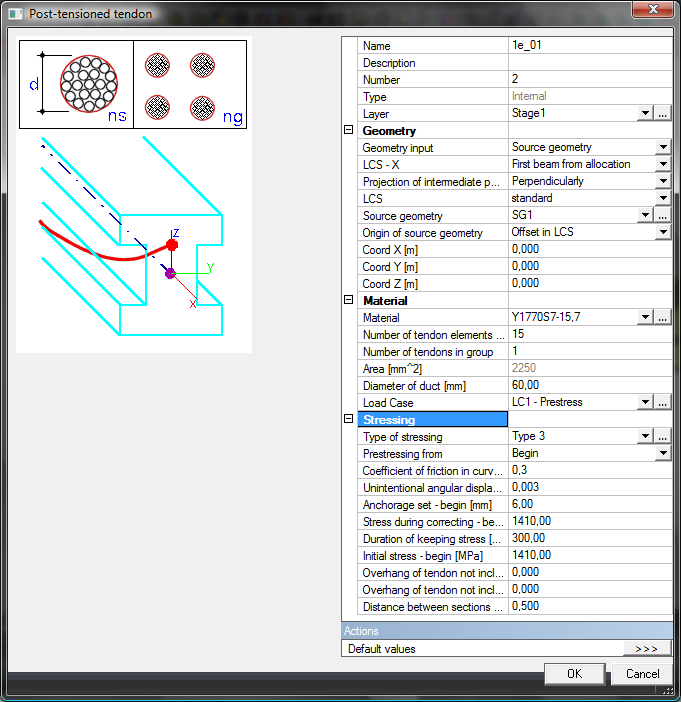
Name
from 1e_01 up to 4e_16 – 30 tendons
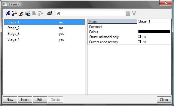
Layer
the four different layers were defined according to construction stages which will be defined later - Stage1, 2, 3 and 4. The name of tendon beginning on number 1 belongs to layer Stage 1 and other...
Geometry input
type Source geometry is used; there are three possibilities of definition of tendon geometry
- Source geometry – user defines geometry in library of SG
- Direct input – user defines geometry of tendon in 3D window directly; the imported geometry from CAD program should be used by this option
- Reference line with source geometry – the source geometry is winded on user defined reference line
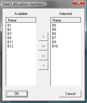
Allocation
the beams (slabs) where tendons are allocated on should be selected
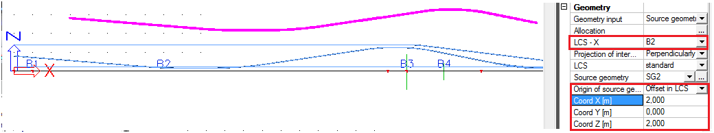
LCS–X
the beam where start the local system of tendons; it could be a first beam from allocation or directly selected beam
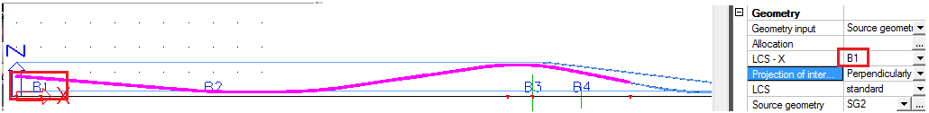
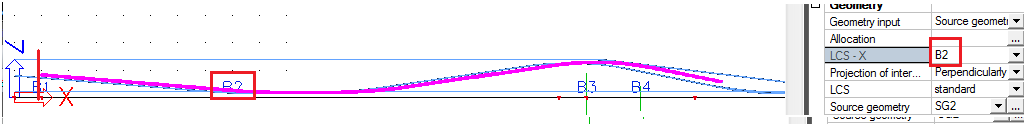
Projection of intermediate points
this option is relevant only in case of Hanging nodes
Proportionally – user defines the length where the tendon effects are projected on
- Way of location – begin
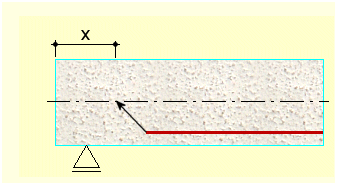
First node – the beginning of projected tendon effects to the beam is from the first node of the allocated beam
Location – distance from the beginning of the beam
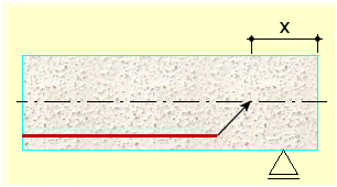
- Way of location – end
Last node – the beginning of projected tendon effects to the beam is to the last node of the allocated beam
Location – distance from the end of the beam
Perpendicularly – tendon is projected directly in perpendiculars to the beams
The hanging nodes are not available for TDA calculation
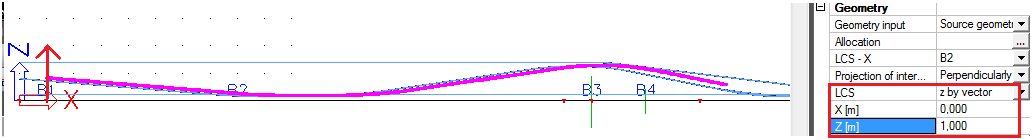
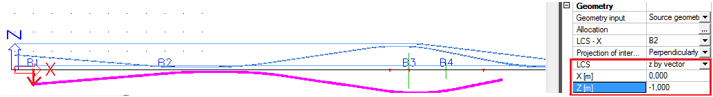
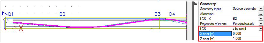
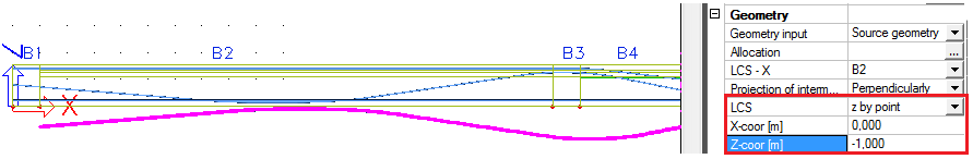
LCS
type of local axis of tendon
Standard – local axis of tendon is the same as local axis of the allocated element
Z by vector – user sets the vector by points X and Z and the direction of z is according to these values
Z by point – user sets the point which shows direction of local coordinate system
Z from UCS – XXX
Source geometry
30 types of SG will be defined by user
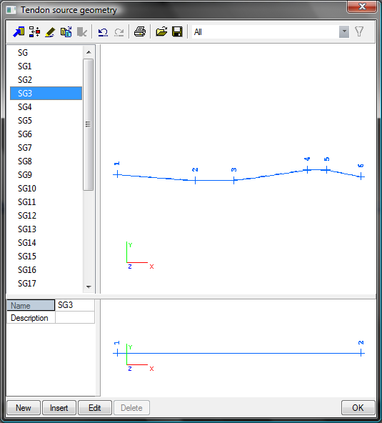
The source geometry should be also imported from user database file.
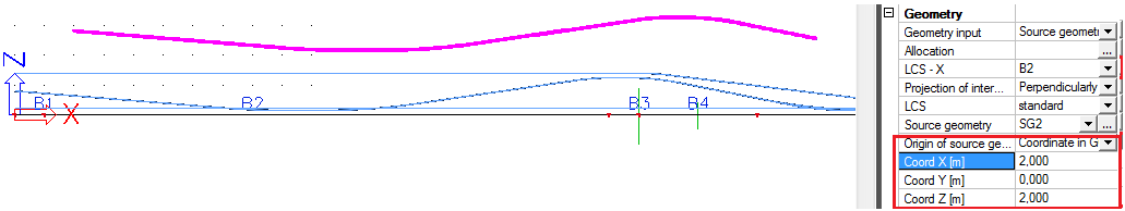
Origin of SG
type of origin of SG
Offset in LCS – the origin can be set related to local coordinates of the beam
Coordinate in GCS – the origin is set related to global coordinates of the file
Material
material Y1770S7-15,7 is used;
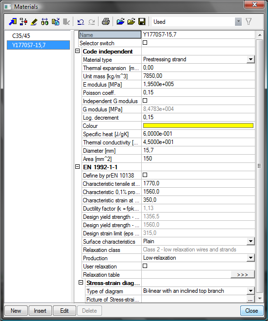
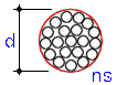
Number of elements in tendon
15 è tendon has 15 strands
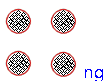
Number of tendons in group
1 è only 1 tendon exists with the same properties and geometry
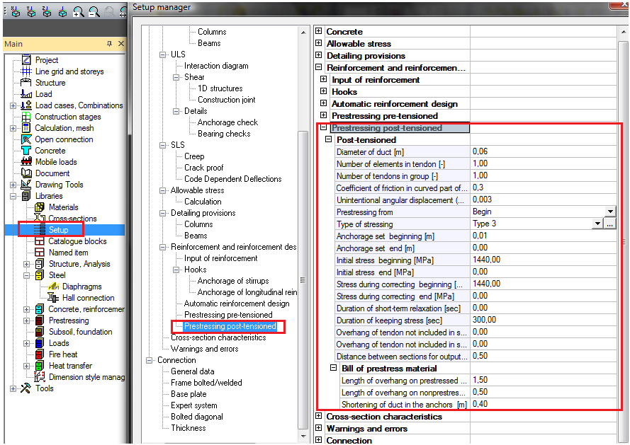
Diameter of the duct
80mm
Stressing
Type of stressing – type 3
Prestressing from – End
Stress during correcting – 1410MPa
Initial stress – 1410MPa
Another value are taken from default settings Libraries>Setup > Prestressing-Postensioned
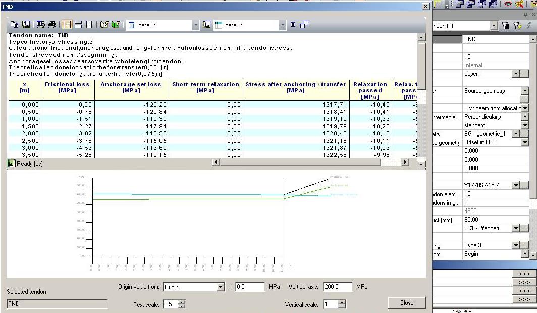
The parameters brief table of tendon is possible to view in document Structure>Tendons>Internal tendons.
The tendon shorterm losses should be dispalyed for each selected tendons
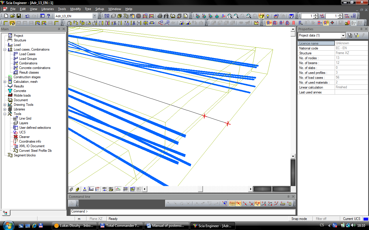
The tendons are drawing in 3D window depending on View parameters settings.
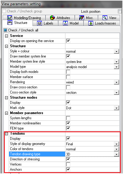
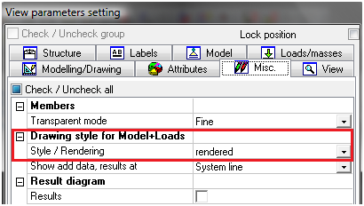
There are three possibilities of displaying of tendons in 3D window – thin line, diameter, 3D. Anchors and directions of stressing are also possible to display. 3D drawing with rendered model can give very nice pictures.
Load
Loadcases
The loadcases have to be defined before construction stages are defined. The following list of load cases will be defined. There are several possibilities of load definition.
Permanent
Type
Standard – necessary for definition of stages in construction stages library, could be empty loadcase used only for definition of stages
Selfweight – loadcase from load of selweight
Loadgroup
Variable
Specification
Standard
Temperature – only thermal load should be defined in this LC
Loadgroup
Link to library of Load group – see (Preparation of mobile load in SEN)
Loads
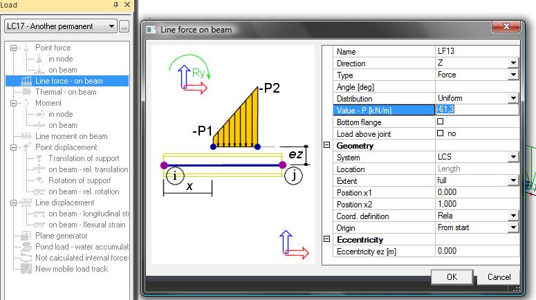
Load is defined according to type of load using Loads. For example - permanent load (road, safety fence and other bridge accessories) is defined in loadcase LC17-Another permanent – type permanent
The definition of the load value is available in Loads>Line force on beam and user defined value -61,3kN/m.
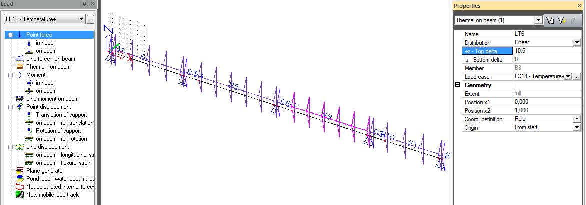
Temperature load
The variable loadcase with specification temperature has to be defined. The temperature load is defined in Load>Thermal on beam.
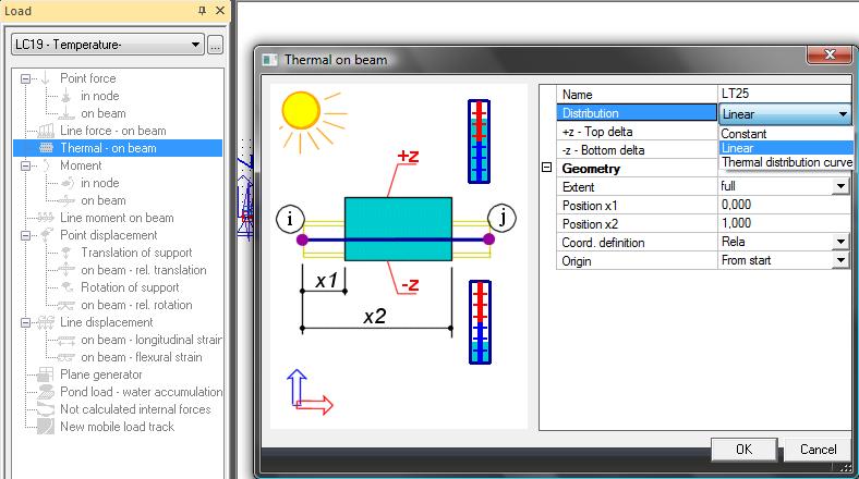
The linear thermal load will be defined.
LC – Temperature–
Top delta - 8°C
Bottom delta 0°C
LC – Temperature+
Top delta +10,5°C
Bottom delta 0°C
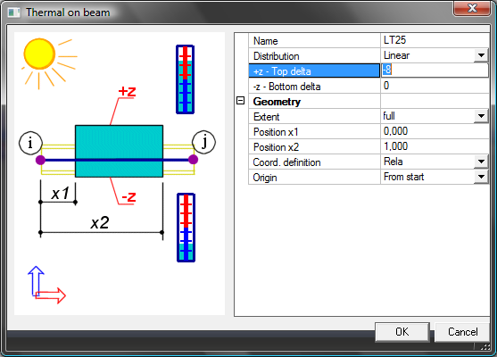
The temperature load is drawn in 3D window following (using triangles).