Check of details and bearing areas
The target of this project is to verify bearing areas of prefabricated concrete elements and check end zones of elements. The end zone of a beam is checked using the Strut-and-Tie analysis (SaT).
The checks of bearing areas are based on chapter 10.9.5 from EN 1992-1-1.
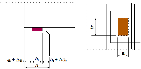
Fig. 1 Figure 10.6 from EN 1992-1-1
The check of the end zone (anchorage) is based on figure 6.27 and chapter 10.9.4.7 for anchorage of reinforcement in the support (EN 1992-1-1). But we could say that both checks are described in the code very shortly and many various cases are not stated there.
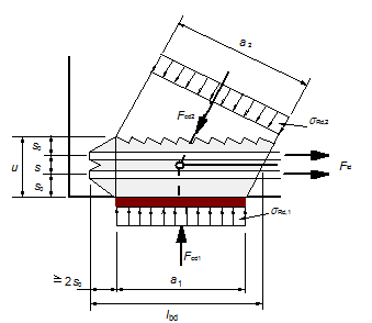
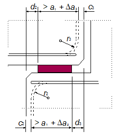
Fig. 2 Figure 6.27 and 10.5 from EN 1992-1-1
Special ULS checks of details of a concrete simply supported beam were implemented in this project.
Although the functionality was implemented for both Frame XYZ and XZ, the internal forces and loads are assumed in one plane XZ of the local coordinate system of beams. The types of the details are restricted to local support areas at the ends of beams. A procedure for calculation of internal forces and checks based on the Strut-and-Tie (SaT) model is described in this document.
The project was split to two basic parts:
- Check of bearing areas – verification of the defined dimension of a bearing
- Check of details – SaT analysis of a standard beam end-zone (SBEZ)
Definition of terms
The following terminology should be clear to the users who want to use this module. All values are explained on the Non-direct detail.
- Supported member – member which is supported; it is part of the structure
- Supporting member – member which supports the structural member; it can be fictive or real
- Interface material – material between supported and supporting member, bearing material
- Length of support (a) – it is total length of the support
- Effective length of support (a1;b1) – it is the length of the support, which is able to carry load from the supported member
- Ineffective length of the supporting member (a2) – it is the distance from the edge of the supporting member to the effective length of the support
- Ineffective length of the supported member (a3) – it is the distance from the edge of the supported member to the effective length of the support
- Tolerance of supporting member Δa2
- Tolerance of supported member Δa3
- Partial tolerance for calculation of design value of supporting member Δa2/
- Partial tolerance for calculation of design value of supported member Δa3/
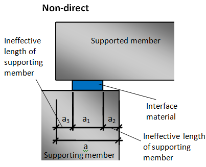
Fig. 3 Explanation of values in end zone
Before we can solve the issues related to SaT we have to define the details with their bearing areas checks.
Check of bearing areas - Standard Beam End Zone (SBEZ)
The program supports three basic types of standard beam end zone. These types are defined by the user using the SBEZ data:
| Direct dry | direct contact between two members without interface material |
| Direct wet | direct contact between two members with wet interface material (mortar or concrete) |
| Non-direct | another element is inserted between the supported and supporting member; the element can be concrete, steel, neoprene.... |
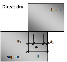
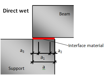
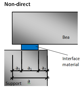
Fig. 4 Three basic types of SBEZ
Check of details - why do we use SaT analysis
Each concrete structure could be divided to two groups of regions. The design of B (Bernoulli or Beam) region is well understood and the entire flexural behaviour can be predicted by simple calculation. On the other hand, even for the most often used examples of D (Disturbed or Discontinuity) regions (such as end zone, deep beams or corbels), engineer's ability to predict the capacity is either poor (empirical) or requires substantial computation effort (finite element analysis) to reach an accurate estimation of the capacity. Examples of the discontinuity areas are shown in the figure.

Fig. 5 Typical examples of the B and D regions
Definition of details
The concept of data definition is very similar to connections in steel structures. Additional data are defined in the structure and then the data check themselves. No additional check service is needed.
There are new items in the Concrete Advanced tree.
SaT details
| Support zones | definition and check of one detail |
| Check of details | check of all details in the project |
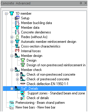
Fig. 6 Concrete tree
Procedure for definition of SBEZ data
Because this check is very different from other standard concrete checks, the procedure of working with the SBEZ data is described in the following points. The following procedure must be followed strictly:
Definition of stages if SBEZ data are required in some stage
User selects SBEZ detail from the concrete tree
Property of SBEZ data dialog appears
User defines property of the SBEZ detail – combination, position of details, type of detail
User selects the beam where SBEZ data are defined on
After definition of data the following condition has to be satisfied:
- Support has to exist in the user defined position of the detail
- Support has to exist in the user defined construction stage
- Support has to be at the end of the beam – SBEZ data are not possible on intermediate support
When the conditions above are not fulfilled, then the warning is given to the user: “The detail doesn’t correspond to the structure, no support was found in selected section.”
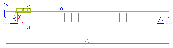
The data are displayed in the 3D window with their own view flag
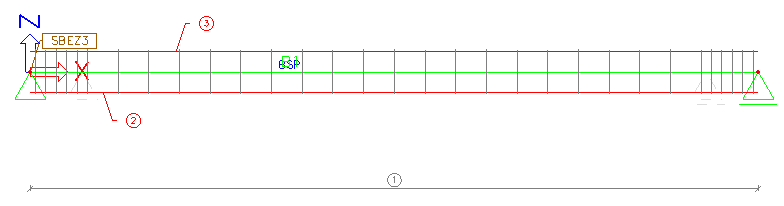
Fig. 7 SBEZ data defined on the beam in 3D window
User selects the SBEZ data and using the refresh button the check of bearing areas and the check of detail are performed.
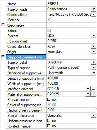
Property of the SBEZ data
The properties of the detail are divided to three parts:
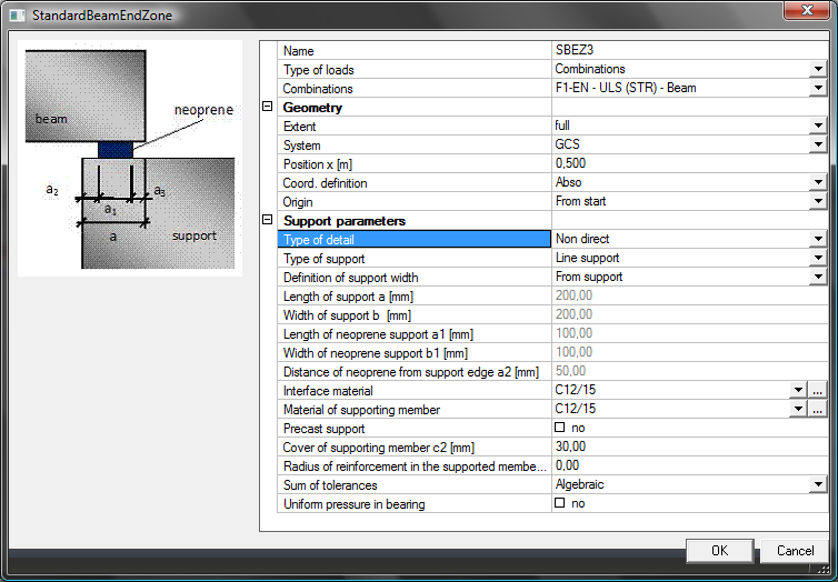
Fig. 8 Property of the SBEZ data
Support parameters
The properties of the detail (support parameters) depend on the type of the selected detail.
Type of detail - We distinguish three basic types of SBEZ details:
- Direct dry
- Direct wet
- Non-direct
Some values in Support parameters are filtered according to the selected type of detail. They are shown in the next table.
| Property depending on type of support | Direct-dry | Direct-wet | Non-direct |
|---|---|---|---|
| a - Length of support | x | x | x |
| a1; b1 - Effective length and width of the support | x | ||
| a2 – Ineffective length of the support | x | ||
| Interface material (neoprene, mortar....) | x | x |
Tab. 1 Property depending on type of support
Type of support – the type of support is necessary for the calculation of the minimum dimension of the detail according to tables 10.2 and 10.3 from [1].
Standard EN 1992-1-1
- Line support
- Purlins (concentrated)
- Ribbed floors (concentrated)
- Concentrated support
Definition of support width – the program is able to read dimension of the detail directly from the support dimensions; There are values a and b in case of Non-direct support
Point support – width of support is a = b
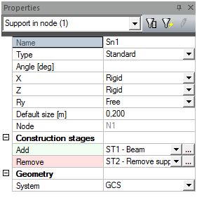
Fig. 9 Setting for temporary support
Beam, column – dimensions of elements a = b are dimension of the beam (column)
| Type of support | a | b | a1; a2 | b1 |
|---|---|---|---|---|
| Direct dry | read | a | - | - |
| Direct wet | read | a | - | - |
| Non-direct | read | a | user defined | user defined |
Tab. 2 Dimension of support for point support
| Type of support | a | b | a1; a2 | b1 |
|---|---|---|---|---|
| Direct dry | read | read | - | - |
| Direct wet | read | read | - | - |
| Non-direct | read | read | user defined | user defined |
Tab. 3 Dimension of support for beam, column support
Material of interface – it is necessary for calculation of bearing material strength
| Type of support | Concrete | Steel | Mortar | Neoprene |
|---|---|---|---|---|
| Direct dry | ||||
| Direct wet | x | x | ||
| Non-direct | x | x | x |
Tab. 4 Dimension of support for beam, column support
Materials Mortar and Neoprene are not available in SCIA Engineer.
Material of supporting member – it is necessary for the calculation of the minimum allowed ineffective length of the support from table 10.3 from [1].
| Type of support | Concrete | Steel | Masonry |
|---|---|---|---|
| Direct dry | x | x | x |
| Direct wet | x | x | x |
| Non-direct | x | x | x |
Tab. 5 Material of supporting member
Material Masonry cannot be used in SCIA Engineer.
Sum of tolerances – the program distinguishes between two calculations of tolerances (see 3.1.3)
- Algebraic
- Quadratic
Precast support – this option appears only for supporting material concrete; it is needed for the calculation of deviation Δa2 (see table 10.5 [1].)
Values r2 and c2 - the values of the radius of reinforcement and concrete cover are related to the supporting member; they are available only for concrete as the material of supporting member
| Material of support | r2 | c2 |
|---|---|---|
| Concrete | x | x |
| Steel | ||
| Masonry |
Tab. 6 Definition of radius and cover of supporting member depending on material
Bearing pressure uniform (10.9.5.2(3)) - When check box is switched OFF, then value b1 is limited by 600 mm. Higher value cannot be used for the calculation.
Isolated members (10.9.5.3(1)) - When this check box is switched ON in, then values in tables 10.2-10.4 will be increased by 20 mm.
- This check box is not available when line support is selected
Direct dry
Dimensions of direct dry support are defined only by the total length (a) of the support. Other parameters are calculated automatically.
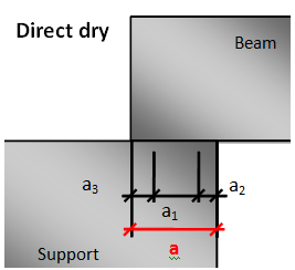
Fig. 10 Direct dry support
Direct wet support
Dimensions of direct wet support are defined only by the total length (a) of the support and by material of the interface. Other parameters are calculated automatically.
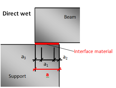
Fig. 11 Direct wet support
Non-direct support
Dimensions of non-direct support are defined by the total length (a) of the support and effective dimensions (a1; b1) of support and ineffective length of the support (a2). The ineffective length of the supported member (a3) is calculated automatically.
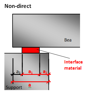
Fig. 12 Non-direct support
Limitation for definition of support
The following conditions should be fulfilled during definition of SBEZ data or during changes of SBEZ data in the property dialog. The limitation also depends on the type of support.
- A support has to exist in the user defined position of the detail
- A support has to exist in the user defined construction stage
- A support has to be a nodal support – SBEZ data are not possible on intermediate supports
Temporary support
The temporary support is the support which is removed during construction stages. It is recognized automatically. When the support is temporary, then user defined value a is equal to value a4. The value a4 is measured from the end of the beam on which the SBEZ data are located. The following condition has to be fulfilled.
Is the support temporary or not? If YES then
xsup ≤ a4
where,
xsup is the x coordinate of the SBEZ data.
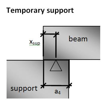
Fig. 13 Bearing length for temporary support
Direct wet or dry support
For the final direct wet or dry support the following conditions are calculated. The minimal value of a2 (from table 10.3 [[1]]) and maximal value a3 (from table 10.4 [[1]]) are determined. The value a1,lim is calculated during the user definition of SBEZ data and it is checked each time when value a is changed in the SBEZ data.
a1,lim = a – (a2,min + a3,max)
The limitation during the definition of SBEZ data is:
a1,lim + a3,max ≥ xsup ≥ a3,max
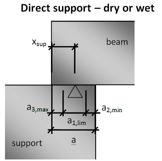
Fig. 14 Bearing length for direct dry or wet support
Non-direct support
The same verification as for the final direct dry or wet support is performed for non-direct support, but value a1,lim is not calculated, because values a2 and a3 are known as user defined values.
The limitation during the change of the defined SBEZ data is:
a1 + a3 ≥ xsup ≥ a3
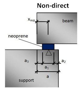
Fig. 15 Bearing length for non-direct support
Check of bearing areas
Calculation of nominal, design values and tolerances
The user defines nominal dimensions of details (a, a1, b1…). Checks of bearing areas are performed using design values of dimensions, which take into account tolerances and “inefficient” parts of the concrete. Design values of the support are marked with subscript d. There are little different design values for the check of bearing areas and for the checks of detail (SaT).
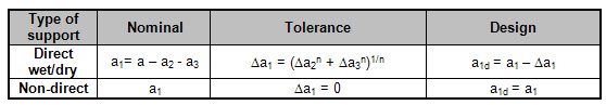
Direct wet / dry support - nominal, design values and tolerances
Value a is defined by the user, no check will be performed and values a2 and a3 come from tables 10.3 and 10.4 EN 1992-1-1 as minimal recommended values and a1 is calculated. Value a2 is determined from table 10.3 for Ed = fRd (for fRd see 3.2.1).
Value n depends on the type of tolerances set in parameters of detail.
- Algebraic – n = 1
- Quadratic – n = 2
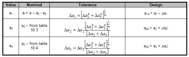
Tab. 7 Nominal and design values of direct support
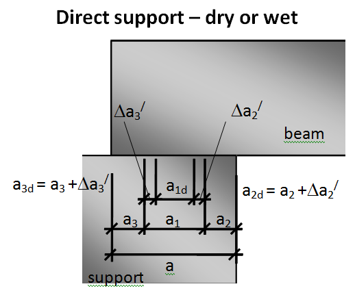
Fig. 16 Nominal and design values of direct support
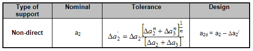
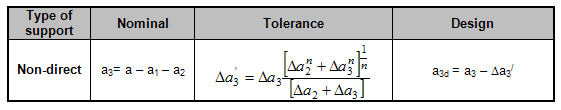
Non-direct support - nominal, design values and tolerances
Values a, a1, a2 are defined by the user, and value a3 is calculated. Value a1 is without tolerance because it is fixed value.
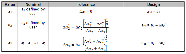
Tab. 8 Nominal and design values of non-direct support
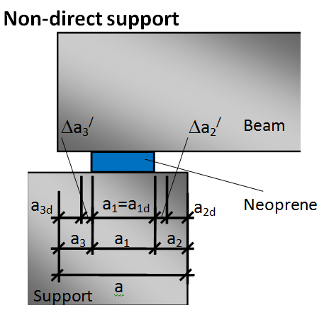
Fig. 17 Nominal and design values of non-direct support
Calculation of tolerances
The tolerances are calculated automatically by the program. It is possible to select the way of calculation of tolerances (algebraic, quadratic) in the SBEZ data (see 2.2.1).
Tolerance of supporting member Δa2
Tolerance Δa2 is determined according to table 10.5 from [[1]].
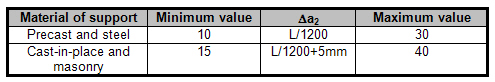
Tab. 9 Recommended values for tolerance Δa2
A precast or cast-in-place support is determined according to check box. Precast support in the SBEZ data see 2.2.1 (this option appears only if concrete material is selected as supporting material.
Masonry material is not available in the current version of the program.
Value L in the formulas above is the length of the span. The length of the span is determined automatically by the program depending on the existence of the “continuous beam” object.
- Continuous beam is used. The detail is defined on the beam and the program determines the length of the span where the SBEZ data are defined. The spans are automatically updated according to construction stages on the continuous beam.
- Continuous beam is not used, then it is the distance between two neighbour active supports near the member where the SBEZ data are defined.
Tolerance of supported member Δa3
Tolerance Δa3 is determined according to 10.9.5.2(1) from [[1]].
Δa3 = Ln / 2500
Where
Ln is the length of the member. Length of the member is automatically determined by the program depending on the existence of the members. It is the length of the longest member in the selected stage between active supports, where the data are defined.
Check of bearing areas and strengths
For the proper function of the bearing areas several checks have to be satisfied. These checks are focused on the limited dimension of the bearing and limited strength in the bearing. Following checks are performed
- Check of bearing strength σEd/fRd (10.9.5.2(2))
- Check of bearing length a1(10.9.5.2 – Table 10.2)
- Check of ineffective distance from outer end of supporting member a2 (10.9.5.2 – Table 10.3)
- Check of ineffective distance beyond outer end of supported member a3 (10.9.5.2 – Table 10.4)
- Check of minimal bearing length for temporary support a4 (only for DTU 4.3)
Not all checks are done for each type of detail. The checks are performed according to the type of support as follows
| Check |
Direct wet / dry |
Non-direct |
|---|---|---|
| Bearing strength | x | x |
| a1 | x | x |
| a2 | x | |
| a3 | x | |
| a4 | x |
Fig. 18 Check performed according to type of detail
Check of bearing strength
The bearing stress (σed) is calculated from the acting reaction in the support and verified against bearing strength (fRd) calculated according to 10.9.5.2 (2). The bearing stress σed is calculated using the following formula.
σed = FEd / (a1d.b1)
Where,
FEd is the support reaction
a1d, b1 – design value of length and nominal value of width
The bearing strength fRd is determined by following formulas
Direct dry
fRd = 0,3* fcd for Direct dry (see 10.9.4.3)
Non-direct
interface material – concrete, steel, neoprene
fRd = 0,4* fcd
interface material – mortar
fRd = fbed ≤ 0,85*fcd
Neoprene and Mortar materials are not available in the current version of the program.
Where,
fcd is the lower of the design compressive strengths for supported and supporting member –time dependant value
fbed is the design compressive strength of bedding material – interface material defined by the user
The result is Check value = σed/fRd
If σed/fRd ≤ 1,0 — OK
If σed/fRd > 1,0 — NOT OK, “Bearing design stress is higher than bearing strength according to table 10.9.5.2 EN 1992-1-1”
| FEd | acting reaction |
| σed | bearing stress |
| fRd | bearing strength |
| Checkcalc | calculated value σed / fRd |
| Checklim | limited value from concrete setup, default 1.0 |
| a1,d | design value of bearing length |
| a1,rec | recommended value of bearing length |
The following values are available in the Table composer: a1; b1; fcd; fbed
Check of bearing length (a1d)
Verification of distance a1d with recommended value a1,rec depending on ratio of σed/fcd according to table 10.2 is performed. For direct support we calculate value a1d and check it against table 10.2. For non-direct support we check value a1d against table 10.2.
Tab. 10 Nominal and design values
Values a2 and a3 for direct wet or dry support are determined from table 10.3 or 10.4 [1]. Calculation of σed is performed in chapter 3.2.1.
| σed/fcd | ≤ 0,15 | 0,15 – 0,4 | > 0,4 |
|---|---|---|---|
| Line support | 25 | 30 | 40 |
| Support of Ribbed floors and Purlins | 55 | 70 | 80 |
| Concentrated support | 90 | 110 | 140 |
Tab. 11 Recommended value a1,rec from table 10.2 [1].
Effects of isolated members (10.9.5.3(1))
When this check box is switch ON in the SBEZ data, then values in the table above are increased by 20 mm
This check box is not available when a line support is selected.
The result is Check value = a1,rec/a1d
If a1,rec/a1d ≤ 1,0 — OK,
If a1,rec/a1d > 1,0 — NOT OK, “Net bearing length is less than minimum value according to table 10.2 EN 1992-1-1 it is necessary to increase net bearing length”
The following values are available in the Table composer: a1; Δa2;Δa3,fcd; σEd
Check of ineffective length (a2d) of supporting member
Verification of distance a2d according to table 10.3 is performed only for non-direct support. For direct wet or dry support value a2d is determined from table 10.3 from [[1]] according to 10.9.5.2 (1)
| Material of support | Type of support | ≤0,15 | 0,15-0,40 | >0,40 |
|---|---|---|---|---|
| Steel | Linear | 0 | 0 | 10 |
| Concentrated | 5 | 10 | 15 | |
| Reinforced concrete fck ≥ 30 MPa | Linear | 5 | 10 | 15 |
| Concentrated | 10 | 15 | 25 | |
| Plain and reinforced concrete fck < 30 MPa | Linear | 10 | 15 | 25 |
| Concentrated | 20 | 25 | 35 | |
| Masonry | Linear | 10 | 15 | Message; 25 |
| Concentrated | 20 | 25 | Message; 35 |
Tab. 12 The recommended value a2,rec from table 10.3 [1] depend on the ratio σed/fcd.
In case of ratio > 0,4 and support material masonry, the message to the user is issued and values as for concrete fck < 30 MPa are used.
WXXX – “The concrete padstone should be used for this material of support and ratio of stresses according to table 10.3 EN 1992-1-1.”
The result is Check value = a2,rec /a2d
If a2,rec /a2d ≤ 1,0 — OK
If a2,rec /a2d > 1,0 — NOT OK; “Ineffective distance beyond outer edge of supporting device to the edge of the effective area of the support is too small according to table 10.3 EN1992-1-1. It is necessary to increase value a2”
The following values are available in Table composer: a2; Δa2; Δa3, Δa2/; Δa3/, fcd; σEd
Check of ineffective length (a3d) of the supported member
Verification of distance a3d according to table 10.4 is performed only for non-direct support. For direct wet or dry support value a3d is determined from table 10.4 [[1]]. Value a3 is determinated from the user-defined geometry of the structure. This value is compared with recommended value a3,rec from the code table 10.4 [1].
The values from table 10.4 depend on reinforcement in the supported member.
| Detailing of reinforcement | Line support | Concentrated support |
|---|---|---|
| Continuous bars or strand over support | 0 | 0 |
| Straight bars or strands | 5 mm | max(15 mm; c3) |
| Strands or bars “go out” from the beam | 5 | 15 |
| Vertical hooked bars or strands | 15 mm | c3 + R3 |
Tab. 13 Recommended value a3,rec - EN 1992-1-1
| c3 | Concrete cover of supported member |
| r3 | Radius of reinforcement of supported member |
The 1st row in the table is used only for the internal support, not in the case of the end support.
When straight bars and hooks exist together, then the higher value will be taken into account.
Limitations - the formulas in setup are not available in the current version of SCIA Engineer.
The result is Check value = a3rec /a3d
If a3rec /a3d ≤ 1,0 — OK
If a3rec /a3d > 1,0 — NOT OK “Ineffective distance beyond outer edge of supported member to the edge of effective area of the support is too small according to table 10.4 EN1992-1-1”.
The following values are available in a3; Δa2; Δa3, Δa2/; Δa3/
Concrete setup for check of bearing areas
There are new tables according to EN1992-1-1 in concrete setup. This part is situated under Concrete > ULS > Details. This part of the setup is split to two tabsheets.
- Bearing checks
- Anchorage checks
There are tables 10.2, 10.3, 10.4 adapted from [1] where recommended minimal values can be changed by the user.
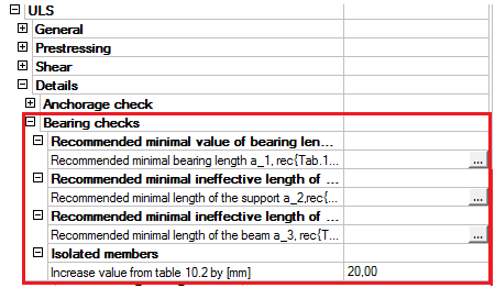
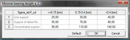
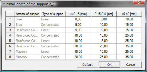
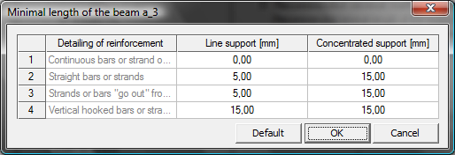
Fig. 19 Concrete setup for Bearing areas
Strut and Tie analysis of SBEZ
The procedure treats each reinforcement layer separately. A concrete strut is associated with each layer, corresponding to its anchorage capacity. Struts are “piled up” until the required force (design shear force) is reached.
The check is performed for prestressing and soft reinforcement together. If the existing reinforcement is not sufficient for that, new reinforcement is added and the check of struts starts again from the beginning. This is repeated until the obtained reinforcement layout is satisfying.
Only when it is not possible to add anchorage reinforcement in order to carry the required force (i.e. there is no space left for additional reinforcement) an error message is issued.
The following terms should be clear to users working with this module. All values are explained in the following table.
Determination of the strut parameters
The parameters of the strut should be determined before the execution of the anchorage check. It is necessary to calculate the design value of the support length a1d and the length of the strut Lstrut. The design support length is calculated by the different way as for the check of bearing areas.
Determination of design value a1d for anchorage check
The design value a1d is calculated for each reinforcement layer because the parameters of the layer can be different, but the program calculates the a1d of the first reinforcement layer and this is taken into account also for another layer.
The design values a1d are different from the values defined for the bearing check. Only the calculated tolerances are taken from the chapter 3.1.3 as for the bearing checks. The design length of the support (a1d) is calculated according to the type of the support in accordance with figure 10.5 from [1].
Direct wet/dry support
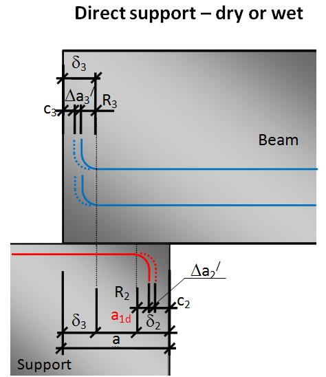
Fig. 20 Value a1d for anchorage check for direct support
Non direct support
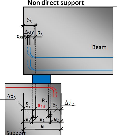
Fig. 21 Value a1d for anchorage check for non direct support
Determination of the length of the strut - Lstrut
The length of the strut is determined according to the type of the support. The design value (a1d) is the initial value for determination of the length of the strut (Lstrut). For the determination of Lstrut the following quantities are used
- Dispersion cone from a1d.
- Position of points A and B
a) Dispersion cone
The program distinguishes between the following types of dispersion cone disp:
Direct bearing – vertical 90 degrees
Non-direct support - default 45 degrees,
- the angle must be used symmetrically on both sides of the cone (because of equilibrium),
- the angle must be adapted (taken greater that 45 degrees) in the case that the cone does not reach the straight part of the reinforcement layer within the concrete of the beam.
The angle of dispersion (θdisp) cone is by default 45 degrees. When the default angle is not available then the angle should be adapted to the dimension of the cross-section with respect to values δ2 and δ3 (see Fig. 26).
The default value of the dispersion cone angle is 45 degrees, and it can be set in the concrete setup dialogue.
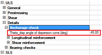
Fig. 22 Concrete setup for dispersion cone
b) Position of points A and B
The value of the length of the strut (Lstrut) depends on the position of the points A and B (see Fig. 26). The points mean the following:
Point A – the end of the straight part of the bar after deducting the tolerances
Point B – corresponds to the starting point for balancing the internal forces in the support – i.e. located exactly above the edge of the effective supporting area.
The length of the strut (Lstrut) will be calculated according to the following formulas
Direct wet/dry support
Lstrut = a1d
Fig. 23 Length of strut (Lstrut) for direct support
Non direct support
Lstrut = a1d + 2*Ldisp
Where
Ldisp - length of the dispersion cone
Fig. 24 Length of strut (Lstrut) for non direct support,
Splitting of reinforcement layers
The reinforcement is split to layers for the anchorage check. There are several rules for considering a layer as a part of a single layer. Only the reinforcement satisfying the following rules is considered as a part of a single layer:
- the same material and
- the same length and
- the same shape and
- located on the same level
For instance, when bars of a different length are located on the same level, they will be treated as 2 separate layers. The bars with the shortest available length should be used first.
Fig. 25 Example of splitting reinforcement layers
SaT calculation method
The procedure of the SaT analysis is described in the following figure. The calculation is made in three steps:
Check of the existing layer
- Check of longitudinal reinforcement
- Check of shear reinforcement
Design required area of
- Longitudinal soft reinforcement (see 4.3.1)
- Shear reinforcement (see 4.3.2)
Performing check with the new reinforcement again
- The procedure of the calculation of each value in the appropriate direction is clear from the following figure.
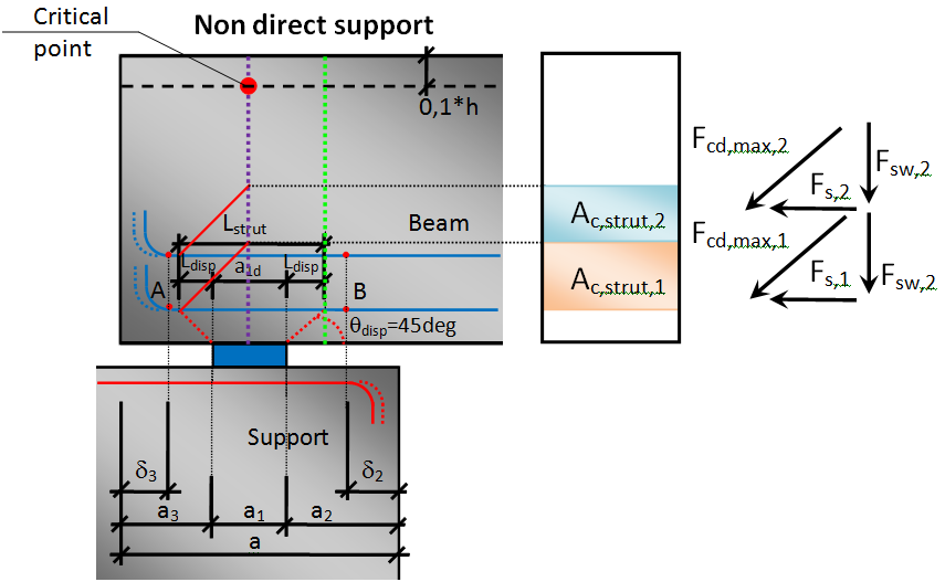
Fig. 26 Values in their direction for Non-direct SBEZ
Calculation of concrete strut
Calculation of concrete strut is divided to two parts:
- Determination of concrete strut area – compression zone
- Calculation of concrete strut capacity
Calculation of compression zone
At the beginning the first layer of reinforcement (with shortest length) is taken into account as the first compression zone
Fs,max,tot (i) = ΣFs,max (i), where i=1...N
Ac,strut = b * (Zsup - Zinf)
Calculation of concrete strut capacity– Fcd,max
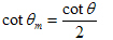
For each concrete strut the maximum force according to the following formulas is calculated :
Fcd,max,i = Ac,strut,i* cos(θm)*σRd,max – capacity in inclined direction
Where:
σRd,max is the maximum stress in the concrete strut see 6.61 [1]
σRd,max = k2 ν´ fcd
The values k1; k2 and ν´ are defined in Concrete > ULS > General.
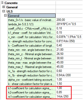
Fig. 27 Concrete setup for strength of concrete strut
Calculation of reinforcement tie with respect to anchorage zone of bars
The forces in bars (Fs) are calculated for each reinforcement bar in each layer. And the total value in the layer is the sum of all forces in the layer. Decreasing is performed only for soft reinforcement and for postensioned tendons. It is not done for pretensioned strands, because the section of detail is situated in the anchorage length and the stress from bending is equal to maximal stress of strands is this section.
Calculation value Fs in the i layer , 
Where:
N the number of bars or strands in i-th layer
Fs the force in strands and longitudinal reinforcement with respect to the anchorage length in ULS in the considered section (capacity of strands according to the position in the anchorage length)
Fs(i) = As σs
Fp(i) = Ap σp
Values σs, σp have to be taken as the capacity of the layer (or strands) calculated from the reduced stress-strain relationships according to the position of the section in the anchorage length.
On the other hand, it is necessary to take into account the effect of bending on the capacity of the reinforcement. Due to the definition of the actual span, the CSS considered at the edge of the support has a non-zero bending moment.
The response in the “green line section” will be calculated under ULS assumptions for the materials, and the stress caused by the flexure will be subtracted from the capacity of the layer (or strands) in the anchorage zone.
σp = σp,orig – σp,bend
σs,= σs,orig – σs,bend
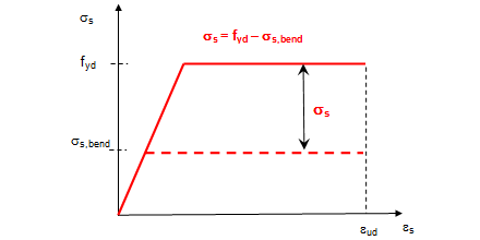
Fig. 28 Concrete setup for decrease of capacity of longitudinal reinforcement due to the stress caused by bending
Where
σp (σs) – the total value of the capacity in the strand (bars) in the anchorage zone (fpd, or fyd)
σp,orig (σs,orig) – the capacity of the strand (bars) in the green line according to the position of the green line in the anchorage zone
σp,bend (σs,bend)– the stress in the strand (bars) from the acting bending moment and normal force in the green line section according to the selected combination;
Decreasing of the capacity of the longitudinal reinforcement by the bending stress can be set in
Concrete > ULS > Details > Longitudinal reinforcement.
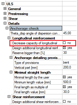
Fig. 29 Concrete setup
Decision of ultimate capacity
The program calculates the ultimate capacity. It means which material fails. Calculation of the force in layer “after reduction” Fs,max:
Failure of concrete strut – the force in reinforcement is bigger than in the concrete strut
fcd,max / cos(θm) < Fs — Fs,max = fcd,max
The total height of the compression zone is used: Zsup = Zsup,max
Failure of tie – the force in reinforcement is lower than in the concrete strut
fcd,max / cos(θm) > Fs — Fs,max = Fs
Calculation a new height of the compression zone.
Calculation of total values for all layers
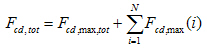
The total value of the maximum forces in the concrete strut fcd,maxtot is calculated as
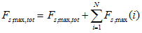
The total value of the maximum forces Fs,max,tot in the layer is calculated as
The total value of the maximum forces Fsw,tot in the vertical direction (for stirrups) is calculated as
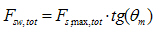
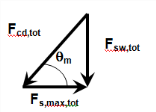
Fig. 30 Equilibrium of forces
Performed check
Two checks are performed.
Check of equation Fsw,tot < Ved and all reinforcement layers (compression zones) are not used
The values Fsw,tot < Ved are compared and all layers are not used
If YES — check the next reinforcement layer
If NO — perform the next check
Check equation Fsw,tot ≥ Ved
The values Fsw,tot ≥ Ved are compared
If NO and all reinforcement layers (compression zones) are used — NOT OK — it is necessary to design additional reinforcement - 4.3.1
If YES — OK – calculation is finished
Calculate Check value <1,0
Ved / Fsw,tot
Output of anchorage check results
The output tables are printed according to the used number of reinforcement layers (struts) in the anchorage check. The following values are printed:
a) Global check of longitudinal reinforcement – check of longitudinal reinforcement
b) Detailed check of longitudinal reinforcement – check of longitudinal reinforcement in each layer
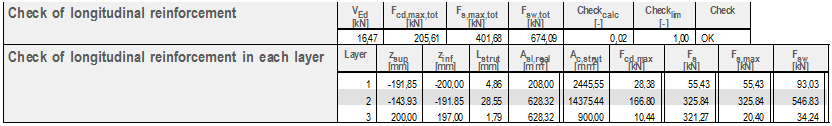
The following values are available in Table composer δ2, δ3, a1d, Zsup, Zinf, As(Ap) σs,tot(σp,tot)σp, σp,bend, σRd,max, θ, θm;
Design of additional reinforcement in detail
Design of additional reinforcement is performed if it is required by the user, if it is specified in the concrete setup. The program can design:
- Additional longitudinal reinforcement - bars
- Additional shear reinforcement - stirrups
Design of additional longitudinal reinforcement
Design of additional longitudinal reinforcement can be split to the following parts:
- Design to the existing layer
- Design between the existing layers
- Design above the existing layers
The parameters (Concrete cover and Diameter) of the design reinforcement are taken from Concrete setup > Design defaults > Beams > Longitudinal reinforcement > Lower.
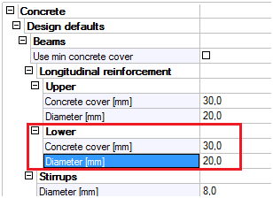
Fig. 31 Parameters for design of additional longitudinal reinforcement
Calculation of area of design additional reinforcement
The calculation of additional longitudinal reinforcement is an iterative solution. The first step is to insert one bar of the default design reinforcement and perform the whole check again. If still not ok, then it is needed to increase the number of bars in this new layer and perform the check again.
The area of the design additional soft reinforcement can be estimated according to this formula:
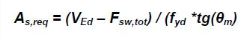
After the design of additional longitudinal reinforcement the calculation procedure is performed again.
Position of additional designed layer
The ratio and reserve are calculated for each layer. The program is searching the zone where Ratio = 1 and Reserve > 0. Where Ratio = Fs,max / Fs; Reserve = (fcd,max – Fs,max) / fcd,max
Start searching from the lowest compression zone upwards and design to this area an additional soft reinforcement.
This step is not possible for prestressed layer.
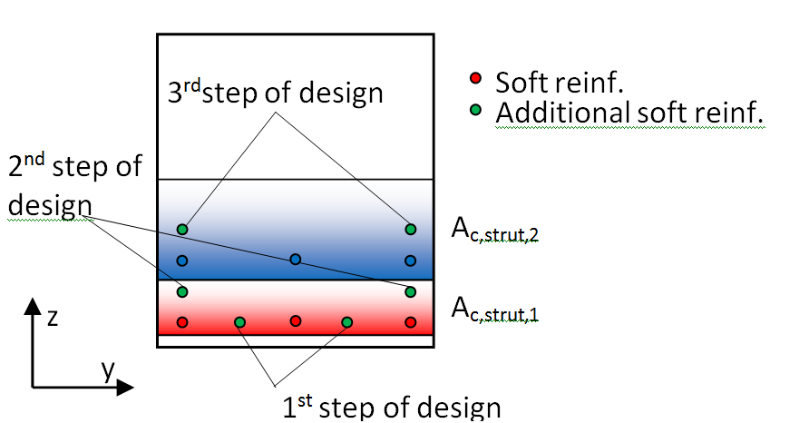
Fig. 32 Design additional reinforcement in nonprestressed cross-section
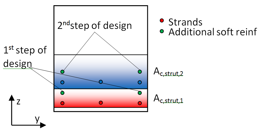
Fig. 33 Design additional reinforcement in prestressed cross-section
Concrete setup
There are several new options related to the design of additional longitudinal reinforcement in the concrete setup. These settings are situated in Concrete > ULS > Details > Anchorage check:
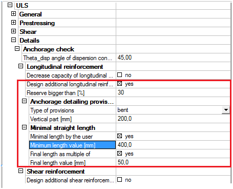
Fig. 34 Concrete setup for design of additional longitudinal reinforcement
Explanation of values from setup:
Design additional longitudinal reinforcement – If YES, then the design is performed
Reserve bigger than – the existing layer can be used only in case the reserve is bigger than this percentage
Anchorage detailing provision
Type of provision – type of designed longitudinal reinforcement
- Straight
- Bent
Vertical part – active only for type of provision – Bent; the length of bent; it is measured from the horizontal straight part to the top end of the vertical part
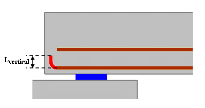
Fig. 35 Vertical part of additional reinforcement
Minimal horizontal straight length by user – YES/NO – if yes then the horizontal straight part will be the minimum of the user defined value
Minimal horizontal straight length value – the user defined minimum horizontal straight part
Final length as multiple of – YES/NO – if yes then the final length of the bar will be a multiple of the user defined value
Multiple of final length – the value which is used for rounding up
The length of additional longitudinal reinforcement, output table
The required additional longitudinal reinforcement has the following parameters. The minimum length (Lstraight, horizontal) of anchorage bars should be measured from the green line. The output is performed for each reinforcement layer (strut).
Value Lbd (anchorage length of longitudinal reinforcement) is not calculated automatically in SCIA Engineer. For the time being the minimum length of lb,min is taken into account max(10Ø;100 mm) – formula 8.6 from EN 1992-1-1.
The default diameters and material of the longitudinal reinforcement are taken from the concrete setup or from the concrete member data if it is defined.
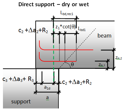
Fig. 36 Minimal recommended length for direct dry or wet
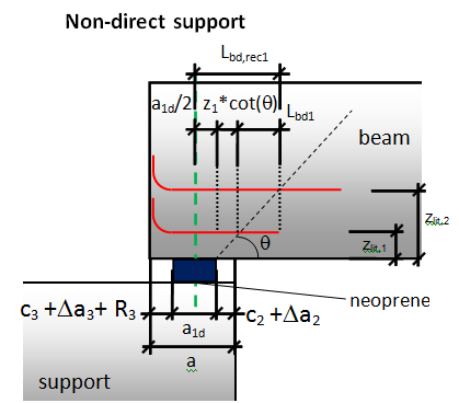
Fig. 37 Minimal recommended length for non-direct support
The final length of the additional longitudinal reinforcement depends on the setting in the concrete setup. There are two possibilities the shape of the additional longitudinal reinforcement (see Fig. 36):
- Straight
- Bent
When the user selects the Bent shape of additional longitudinal reinforcement then the following additional values are calculated:
Mandrel diameter - then mandrel diameter is determined according to the setting in Concrete setup > Detailing provisions > Minimum mandrel diameter bends hooks and loops
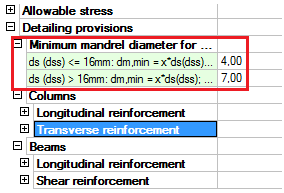
Fig. 38 Concrete setup for determination of mandrel diameter
The following table describes each calculated value and it is also a procedure for calculation of the length of additional longitudinal reinforcement. The final length of the reinforcement is determined as a multiple of the user defined value, the default value is 50 mm. The final length of all additional reinforcement is the longest length from them.
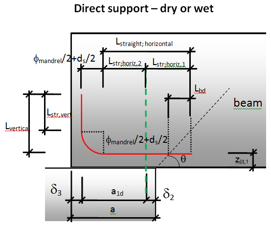
Fig. 39 Length of additional longitudinal reinforcement – direct dry/wet
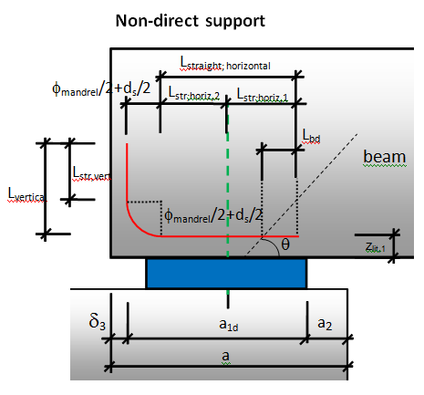
Fig. 40 Length of additional longitudinal reinforcement – non-direct
Output table will be following:
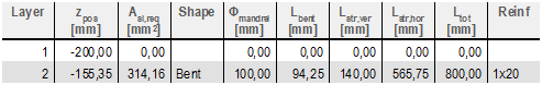
Fig. 41 Output of additional reinforcement
Design of additional stirrups in end beam zone
This chapter is about the design of additional stirrups in the end beam zone due to anchorage of longitudinal reinforcement.
The stability scheme in Fig. 44 is based on a uniform distribution of stirrups along the strut corresponding to each reinforcement layer.
In order to satisfy this condition, the stirrups corresponding to the loads balanced by the layer i must be distributed between the position 0 and xi. The same applies to next layers. Hence the interval [0; xi] includes the stirrups corresponding to the layer i as well as a part of stirrups from layers n of lower ranking, with a ratio :

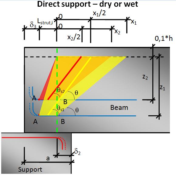
Fig. 42 Stability scheme with several anchorage reinforcement layers for direct dry/wet
The variable angle θs is used different for each layer and it is calculated from the geometry of the end beam zone according to following formula
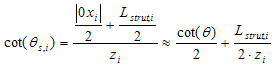
Determination of value z for each layer
The verification of stirrups will be performed for each concrete strut. The distribution of stirrups must be checked for consistency against anchorage reinforcement.
For each compression zone and associated strut, the spacing of stirrups (defined during a regular beam design) should be checked and possibly adapted against the detailing of end-of-beam. The stirrups that are anchored in each strut must be checked with the corresponding lever arm zi = di -0,1 h.
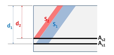
Fig. 43 Effective depth for each layer
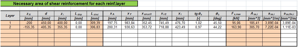
Performing check of stirrups
For each i-th reinforcement layer the required area of shear reinforcement Ass,i is calculated from the longitudinal force in each layer Fst,max,i, which is obtain from the chapter 4.2.3
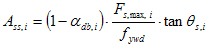
Where
Value θdb,i = 0 for the temporary solution
Value Ass,i is the area of stirrups from ith layer along the distance 0xi
Value ass,i is the area of stirrups from ith layer per 1meter.
Where
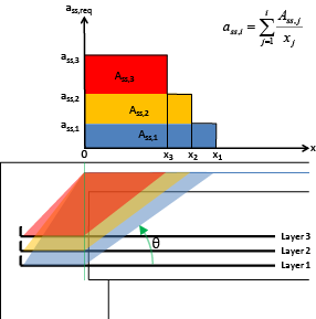
Fig. 44 Distribution of stirrups in the anchorage zone
The values in the table are sorted according to the distance of the zones on the beam (e.g. 0x3; x3x2; x2x1) and the value on the distance.
Distance of the stirrups sss,i will be calculated from required area of shear reinforcement ass,I for the area of one stirrups Ass1 respecting the number of cuts.
The default diameter (dss), number of cuts (nss) and material of the stirrups are taken from the concrete setup or from the concrete member data if it is defined (see Project data and Concrete Advanced > Design defaults > Beams > Stirrups).
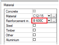
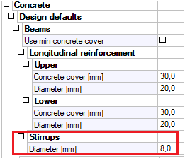
Fig. 45 Parameters of required shear reinforcement
The output is performed for each reinforcement layer (strut) and gives the total required area along the end zone. The maximum check value is presented to the user as the extreme.
The check is performed following Check value = ass,real / ass,req in each zone.
If ass,real / ass,req ≤ 1,0 — OK
If ass,real / ass,req > 1,0 — NOT OK; “The additional shear reinforcement have to be added according to required area.”
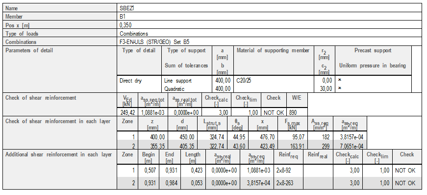
Table composer: xi; θ ;di, h;
Check of details
This service provides the check of all details and gives the global results for all details. The service is situated below the SBEZ data in the concrete tree.
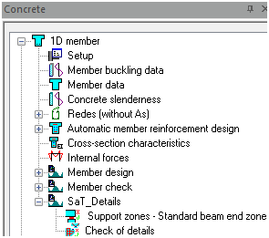
Fig. 46 Concrete tree
Service “Check of details” is used for calculation of “Check value” for all the defined details in the structure. Only ULS combination or classes are offered to the user in the properties. The properties of this service are.
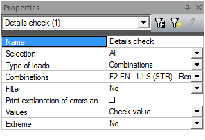
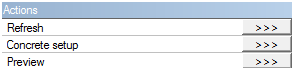
Fig. 47 Property of service check details
Three action buttons are at the bottom of the property dialog:
- Refresh – this button starts the check of all details
- Concrete setup – this is a link to the standard Concrete setup and makes it possible to set the values related to the check of details
- Preview – by this button the calculated results are displayed in a table
The output table is following:
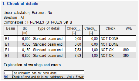
Fig. 48 Check of detail table
Document
The document is divided to several parts by different types of OTX file. There are the following OTX files:
- Bearing checks – all checks related to the Check of bearing areas
- Default – summary of all partial checks in the selected detail; overall check value
- Longitudinal reinforcement – all values related to the check of longitudinal reinforcement
- Parameters of detail – only the property table of a detail, in this OTX it is possible to change parameters of the detail through the document
- Shear reinforcement – all values related to the check of shear reinforcement
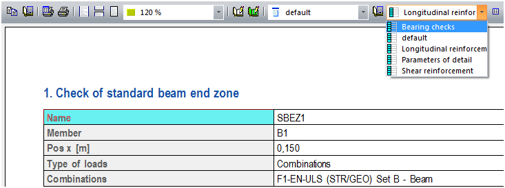
Fig. 49 Type of OTX in the document
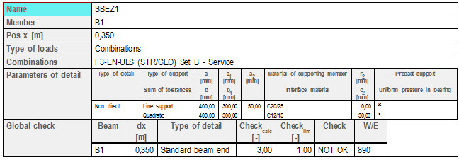
Fig. 50 Default OTX
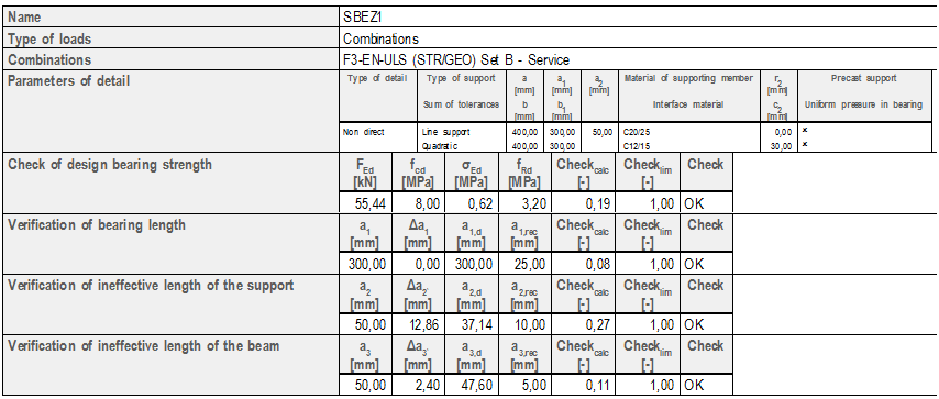
Fig. 51 Bearing check OTX
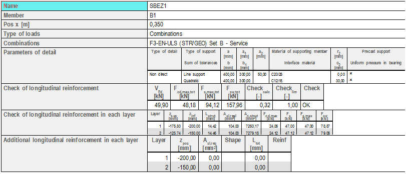
Fig. 52 Longitudinal reinforcement OTX
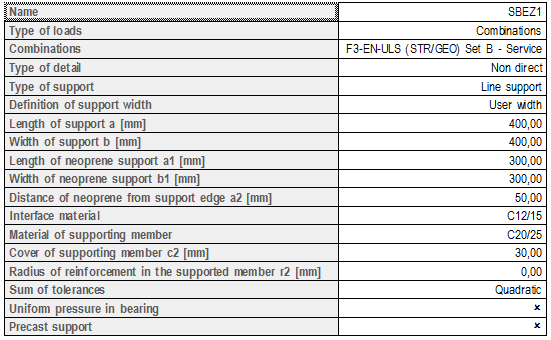
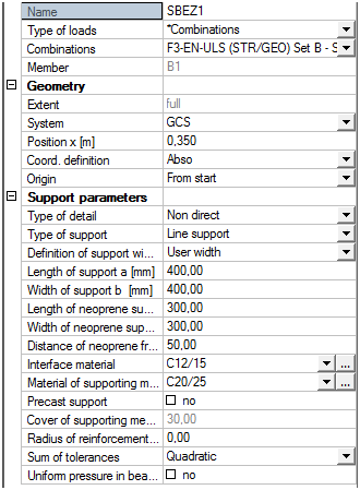
Fig. 53 Parameters of details
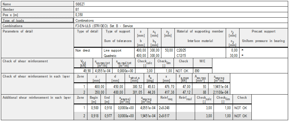
Fig. 54 Shear reinforcement
Restrictions and limitations
There are also some restrictions and limitations for the discussed checks. The user should take into account the following when using this functionality.
- Only the type of detail Standard beam end zone is possible.
- Only frame XYZ and XZ can be used.
- There is no possibility to use material Neoprene, Masonry and Mortar as interface material or material of supporting member.
- Only reaction with an upward direction is taken into account for both the check of bearing areas and SaT analysis.
- The structure has to be modelled as a real structure (with overhangs of beams in the support zone) , no axial scheme is supported in this calculation.
Examples
The theory described above was tested on the following three examples. The results are compared with manual calculations.
Direct dry - prestressed beam with one reinforcement layer
Used CSS with reinforcement layers - Y1770S7-9,3
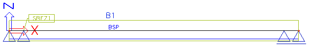
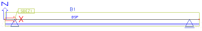
Overview of the structure
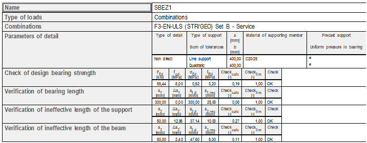
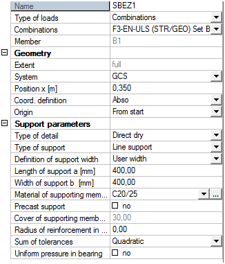
Parameters of detail
Results
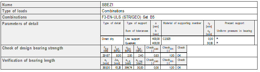
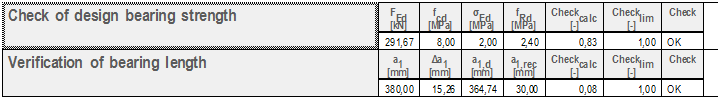
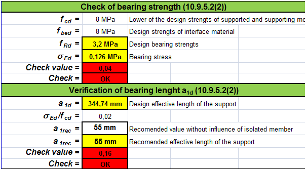
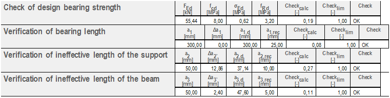
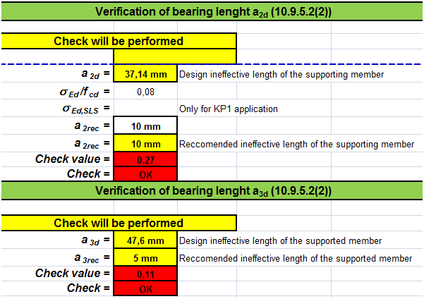
Check of bearing areas
- SCIA Engineer output
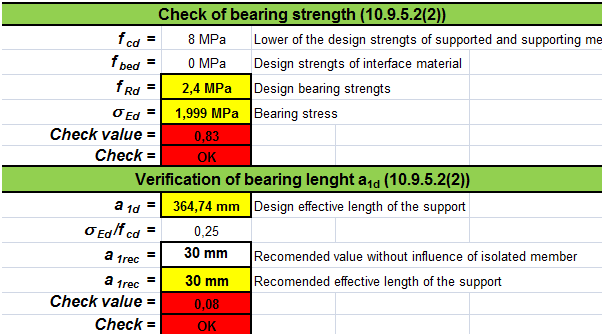
- Manual calculation output
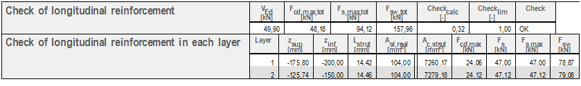
Check of Longitudinal reinforcement
- SCIA Engineer output
- Manual calculation output
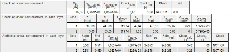
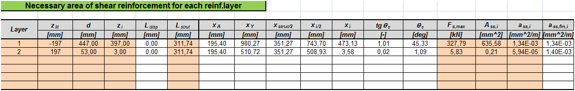
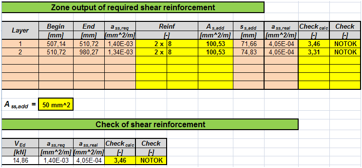
Check of shear reinforcement
- SCIA Engineer output
- Manual calculation output

Direct wet - nonprestressed beam with two reinforcement layer
Used CSS with reinforcement layers - Ø20 B600C
Overview of the structure
Parameters of detail
Results
Check of bearing areas
- SCIA Engineer output
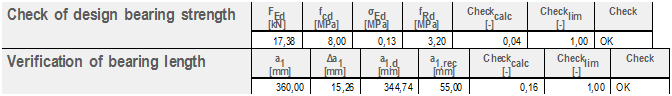
- Manual calculation output
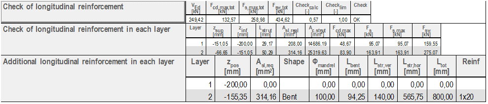
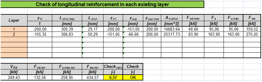
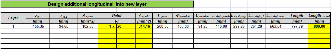
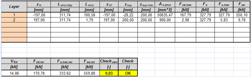
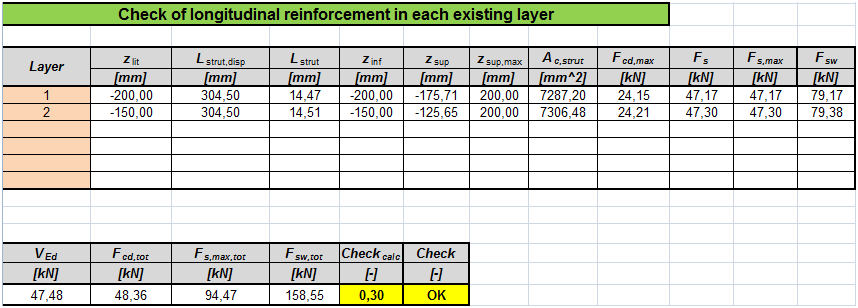
Check of Longitudinal reinforcement
- SCIA Engineer output
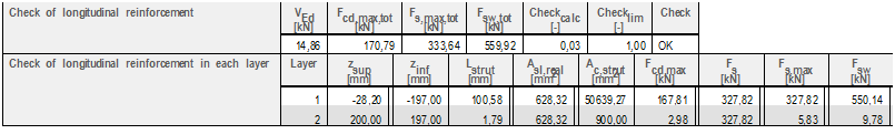
- Manual calculation output
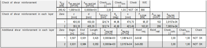
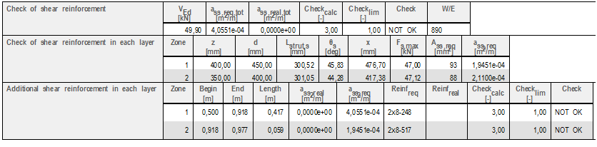
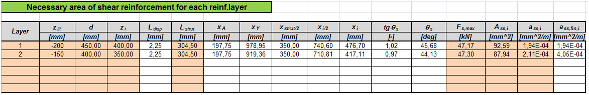
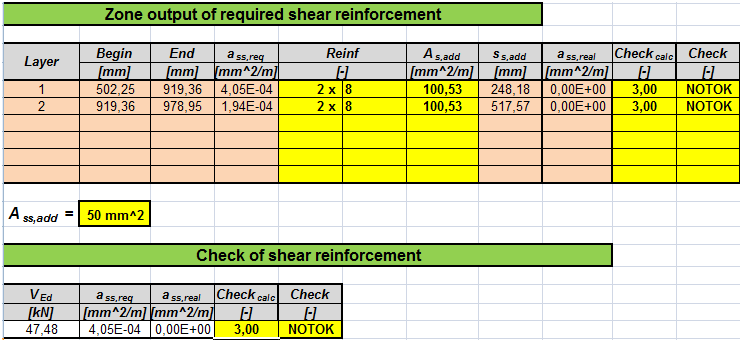
Check of shear reinforcement
- SCIA Engineer output
- Manual calculation output
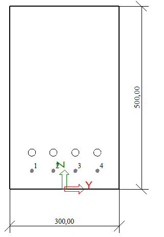
Non-direct - prestressed beam with two reinforcement layer
Used CSS with reinforcement layers - Y1770S7-9,3

Overview of the structure
Parameters of detail
Results
Check of bearing areas
- SCIA Engineer output
- Manual calculation output

Check of Longitudinal reinforcement
- SCIA Engineer output
- Manual calculation output
Check of shear reinforcement
- SCIA Engineer output
- Manual calculation output
Abbreviations
The following abbreviations are used in the document.
| BSP | Beam strands pattern |
| CMD | Concrete member data |
| CSS | Cross-section |
| CZ | Compression zone |
| SaT | Strut-and-Tie analysis |
| SBEZ | Standard beam end zone |
| SEN | SCIA Engineer |
Bibliography
[1] EN 1992-1-1 Eurocode 2, Design of Concrete Structures – Part 1: General rules and rules for buildings, European Committee for Standardization, December 2004.
[2] NF P 19-202-3 Norme francaise, DTU 23.3 P3, juillet 2006
[3] Navrátil, J., Prestressed concrete structures, Akademické nakladatelství CERM, 2006
[4] KP1 New beam system, Synthesis for anchorage and additional bars