Crack control 2D – EN 1992-1-1
The SCIA Engineer program from version 2011 allows users to check crack widths for 2D member according to EN 1992-1-1 .
The main principle of calculation:
- The crack width is calculated for both surfaces of 2D member
- All types of 2D members are supported (plate, shells, wall)
- The crack width is calculated in the direction of the principal stresses at both surfaces of 2D member
- The direction of crack width is shown in the graphical window
- The tension stiffening of concrete between cracks can be taken into account
- The prestressing reinforcement inputted in the 2D member is not taken into account
- The influence of ribs is always taken into account (the internal forces and designed reinforcement in the direction of the rib at the effective width of the rib is zero for 2D member)
- The following load cases/combination/classes are supported
- all types of load cases
- standard SLS combination (linear-serviceability, EN-SLS Char, EN-SLS Freq, EN – SLS Quasi)
- nonlinear combination with Type = serviceability
- class where one or more combinations described above are available
- The crack width can be calculated for the designed reinforcement or user (real) defined reinforcement
Setting of calculation
Before the calculation of crack width can be done, it is necessary to:
- run linear calculation
- check or edit default values in the concrete setup
- input user reinforcement or designed required reinforcement
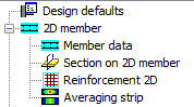
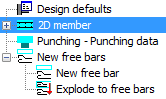
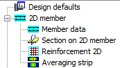
The user reinforcement can be inputted via (see chapter 4.4.1)
- reinforcement 2D
- free bars
- concrete member data (the reinforcement is the same for whole 2D member)
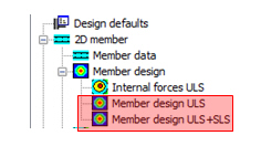
The designed reinforcement can be calculated via two services in tree Concrete Advanced > 2D member
Concrete setup
There are many items in concrete setup, which have influence on the design and check of 2D members. The important parameters, which have direct influence to check cracks, are the following:
- limit value for check,
- limit value of crack width,
- load duration factor.
Limit value for check
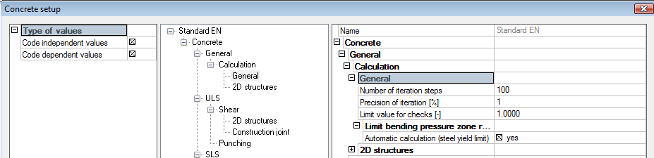
The user can set the limit value for the result of the check. If the calculated check value is greater than the limit value, then the result of the check is OK. Otherwise the result of the check is NOT OK.
This limit value can be set in property Limit value for check (Concrete solver >General > Calculation > General) and this limit value will be used for all types of checks for 1D and 2D members.
Limit value of crack width
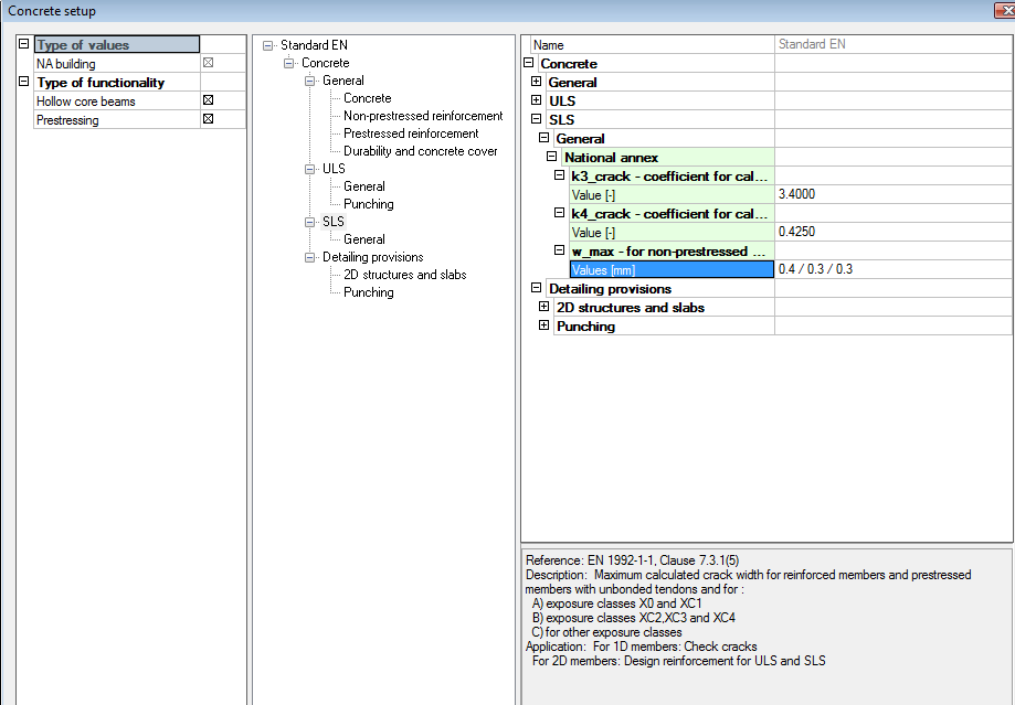
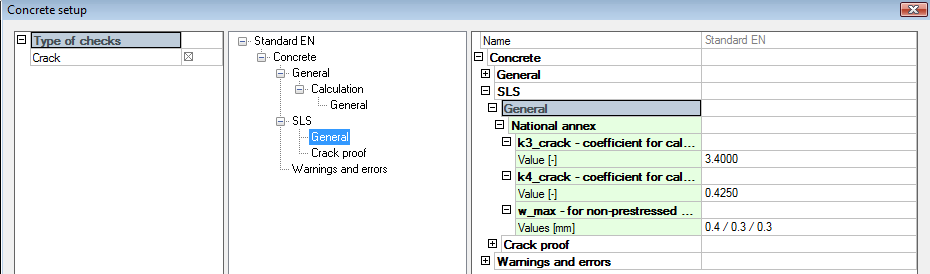
The limit value of crack width is defined in EN 1992-1-1, table 7.1N. The limit value for non-prestressed structure depends only on exposure class and can be set in Manager of national annex (code EN 1992-1-1 > SLS > General > National annex > property w_max for non-prestressed concrete), because the table 7.1.N is only recommended and can be changed in National annexes for some countries.
The exposure class for 2D member can be defined in setup Design default (Design default > Concrete cover > Exposure class), if the concrete member data is not defined on selected 2D member or in Concrete member data, if it is defined on selected member.
The limit crack width can be set directly in service Crack control (tree Concrete Advanced > 2D member > Member check) via action button Concrete setup, where all parameters which have influence on the calculation of crack width for 2D member are available.
Load duration factor
The effect of tension stiffening is taken into account for calculation of crack width of 2D member (chapter 4.6.1.2). The effect of tension stiffening depends on duration of the load, which is expressed in calculation by load duration factor kt . This value can be set in Concrete solver > SLS > Crack proof > group General
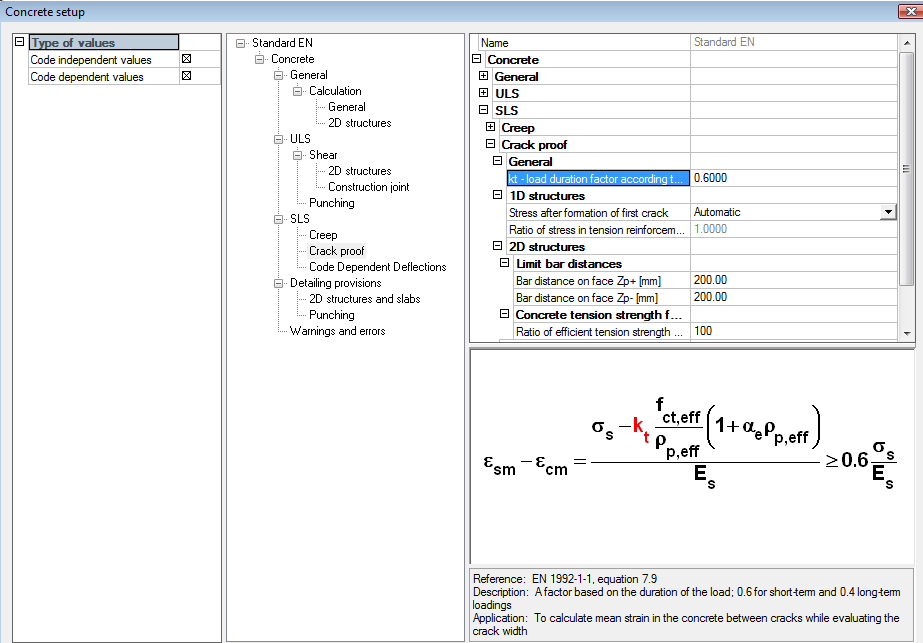
The following values may be used according to code EN 1992-1-1, chapter 7.3.4(2):
kt = 0,6 for short term loading (default value)
kt = 0,4 for long term loading
- The value kt = 0,6 for long term loading in SCIA Engineer should be used:
- for permanent or long-term load cases
- for quasi permanent combinations
- for other SLS combinations in which long term loading predominates
- The value kt = 0,4 for short term loading in SCIA Engineer should be used:
- for variable or short-term load cases
- for other SLS combinations in which long term loading predominates
- the effect of tension stiffening will not be taken into account, if zero value is defined for value kt,
Service for check cracks
Check crack width for 2D member can be done
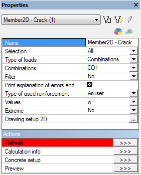
in tree Concrete via service Crack control (tree Concrete Advanced > 2D member > Member check)
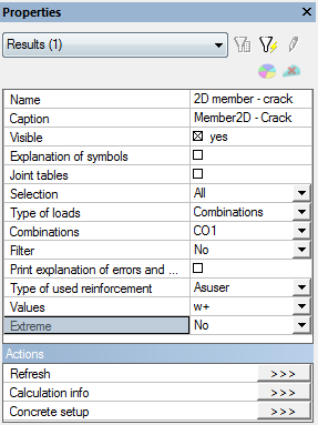
in Document via item Crack control (document > button New > Concrete Advanced > 2D member > Member check)
| Service crack control in tree | Concrete Service crack control in Document |
|
|
Description of the service
This service for the check of crack width in tree concrete or in document is a standard concrete service where the user can select:
which members are to be checked (properties Selection and Filters)
for which loads case/combination/class the members the check will be performed (properties Type of loads). The following load cases/combination/classes are supported (filtered)
all types of load cases,
standard SLS combination (linear-serviceability, EN-SLS Char, EN-SLS Freq, EN – SLS Quasi)
nonlinear combination with type = serviceability
class where one or more combinations described above are available
if the explanation of errors and warnings which occurred during the check will be presented in the numerical output (property Print explanation of errors and warnings). The explanation of errors and warnings is presented under the tables in numerical output. These explanations are available in dialog Calculation info which can be opened via action button Calculation info
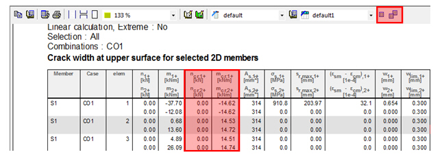
if the explanation of symbols used in tables will be presented in numerical output (property Explanation of symbols). This property is available only in service Crack control in document. The explanation of symbol is presented too above the command line after selecting the cells in the table, see picture below.
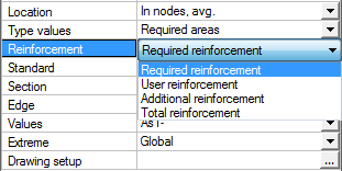
which type of reinforcement will be used for the check of crack width (combo box Type of used reinforcement). The area of reinforcement recalculated to the centre of the FEM element is taken into account and therefore the area of reinforcement in the centre of the FEM element should be calculated before the check of crack width (Location = In centres). There are two possibilities:
- As,tot – is total reinforcement, which has to be designed in the service Member design ULS or Member design ULS+SLS (value Total reinforcement). The total reinforcement is calculated according to formula
As,tot = max(As,user; As,user+As,add )
It follows that if the user reinforcement is not inputted on FEM element (As,user = 0) then only the required reinforcement will be taken into account and the total reinforcement is the same as the additional reinforcement (As,add)
- As,user – only the inputted user reinforcement on FEM element is taken into account. User reinforcement can be defined via
- reinforcement 2D,
- free bars,
- concrete member data (the reinforcement is the same for whole 2D member)
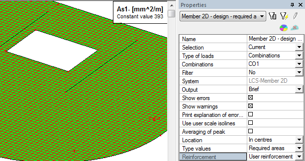
The area of inputted user reinforcement which is used in the check of crack width can be presented in the service Member design ULS or Member design ULS+SLS (value User reinforcement).
The check crack width finishes with error 567 (No reinforcement found in the cross-section), see chapter 4, if
- Type of used reinforcement = As,tot and the area of reinforcement is not designed
- Type of used reinforcement = As,user and user reinforcement is not inputted
Total reinforcement As,tot:
User reinforcement As,user:
which value will be presented in numerical and graphical output (combo box Values). The value is always calculated and presented in the centre of FEM element and for whole FEM element the results are the same. There are available the following values
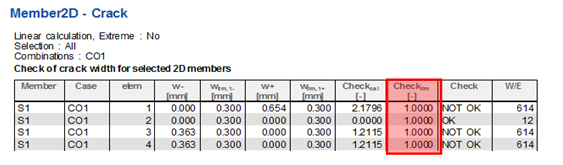
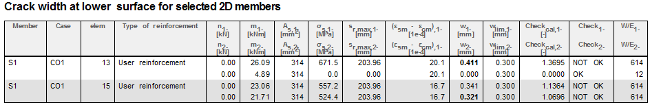
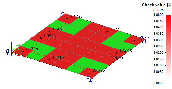
- Check value – the calculated check value for both directions of principal stresses and for both surfaces of 2D member. The unit check will be presented in numerical and graphical window, where
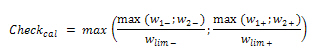
where
wi,± = calculated value of crack width in the i-th direction of principal stresses at lower (-) or upper (+) surface of 2D member, see chapter 3.6
wlim± = Limit value of crack width at lower (-) or upper (+) surface of 2D member loaded from concrete setup, see chapter 2.1.2
Note
The bold values in explanation of symbols can be presented in numerical output for check of cracks
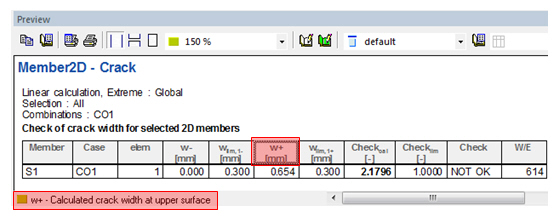
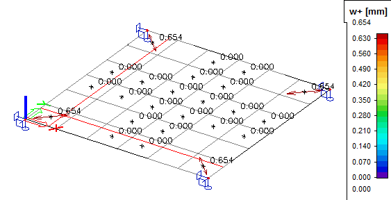
w+ - the crack width at upper surface (in direction of positive value of z-axis of LCS). The direction and size of crack width will be presented in graphical window where direction of crack is perpendicular to direction of principal stresses
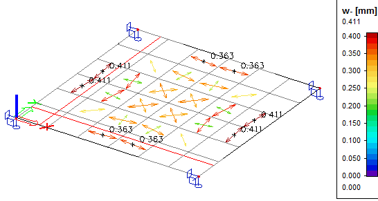
w- - the crack width at lower surface (in direction of negative value of z-axis of LCS). The direction and size of crack width will be presented in graphical window where direction of crack is perpendicular to direction of principal stresses
More comp. – only numerical output is available for this option and tables for selected values will be presented in numerical output
how the results will be presented in numerical output (properties Extreme). There are three possibilities, see [4]:
- No (results for all FEM elements will be displayed on selected 2D members)
- Member (only elements with maximum results for each of selected 2D member will be presented)
- Global (only elements with maximum results for all selected 2D members will be presented)
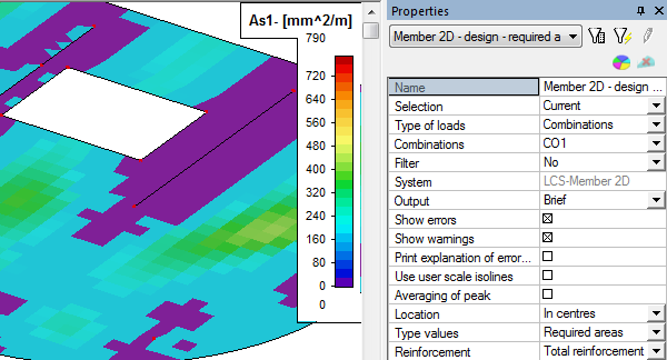
how the values will be presented in graphical output (properties Drawing setup 2D). The drawing setup depends on selected value, where for Check value and for values w+, w- different drawing setup is used.
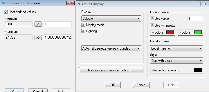
- For Value=Check value the default drawing setting on the picture below is used, it means that FEM element with check value lesser than 1 will be filled with green colour, other elements with red colour. In the legend only values greater than 1 will be presented. For presentation of all values in legend it is necessary to switch off check box User defined values in dialog Maximum and minimum settings.
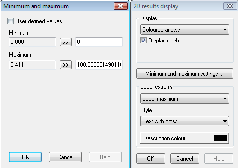
- For Value=w+/w- the default drawing on the picture below is used, it means crack width is drawn as coloured arrows in direction of principal stresses and the size and colour of arrow depends on size of crack width. There is presented crack width according to colour in the legend too.
Note
The crack width for envelope combinations are calculated only for two extreme groups of forces (minimum and maximum). These groups of forces are finding provided the maximum principal stresses. It follows, that for some cases, extreme value of crack width need not be found, because crack width depend on area and direction of reinforcement too and this is not taken into account for finding extreme forces.
Numerical output
The numerical output is available after clicking on action button Preview in service crack control in tree Concrete. The numerical output depends on selected value ( three tables are available).
Table for Value = Check value
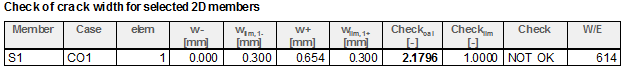
Table for Value = w+
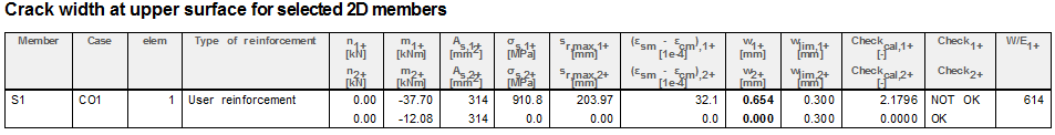
Table for Value = w-
Note
- Existing table can be edit via icon Table composer
 (after clicking on table in numerical output) or via double clicking on the header of the table, see picture below
 - The new table can be created via icon Table manager


Graphical output
The values presented in graphical output depend on selected value in properties of the service. (three graphical output are available). The graphical output is not available for Value = More comp.
Graphical output for Value = Check value
Graphical output for Value = w+
Graphical output for Value = w-
Theoretical background
The module for calculation crack width for 1D member will be used for calculation of crack width for 2D member, therefore the internal forces and area of reinforcement in direction of principal stresses have to be calculated. The crack width will be calculated in centre of each FEM element and the forces from centre of each FEM element will be used for calculation
Steps for calculation internal forces and area of reinforcement:
- the stresses in direction of axis x and y of LCS for both surfaces of 2D member will be calculated
- the angles of the first principal stress for both surfaces of 2D member will be calculated
- the internal forces in centre of FEM element will be recalculated to direction of principal stresses
- the area of reinforcement will be recalculated to direction of principal stresses
- normal stresses (occurring of crack width) in direction of principal stresses is checked
- crack width in direction of principal stresses is calculated
Calculation stresses
The stresses at upper (index +) and lower surfaces (index -) will be calculated according formulas below
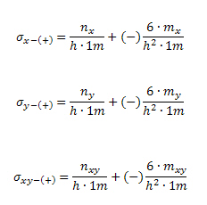
where
nx(y) normal force in centre of the FEM element in x(y) direction
mx(y) bending moment in centre of the FEM element in x(y) direction
nxy membrane shear force in centre of the FEM element
mxy twisting moment in centre of the FEM element
h thickness of the FEM element in centre of the FEM element
- The forces in centre of FEM element can be presented in service Member 2D – Internal forces (tree Result >2D members) or in service Internal forces (tree Concrete Advanced > 2D member > Member design) for Location = In centres
- The stresses at both surface of 2D member can be presented in SCIA Engineer in service Member 2D- stresses (tree Result >2D members) for Location = In centres and for Type of forces = Basic magnitudes
Calculation angle of the first principal stress
Angle of the first principal stress, it means angle between first principal stress and x- axis of LCS system , is calculated according to formula:
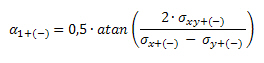
where
σx+(-) stress in direction of x-axis of LCS at upper (+) or lower (-) surface
σy+(-) stress in direction of y-axis of LCS at upper (+) or lower (-) surface
σxy+(-) shear stress at upper (+) or lower (-) surface
The angle of the second principal stress is perpendicular to direction of the first principal stress, it follows:
α_(2+(-))=α_(1+(-))+90deg
The angle of the first principal stress can be presented in SCIA Engineer in service Member 2D- stresses (tree Result >2D members) for Location = In centres, for Type of forces = Principal magnitudes and for Values = Alfa+ or Alfa-
Recalculation forces to direction of principal stresses
The calculated forces in centre of FEM element are recalculated to directions of principal stresses according to standard transformation formulas:
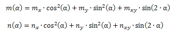
where
nx(y) - normal force in centre of the FEM element in x(y) direction
mx(y) - bending moment in centre of the FEM element in x(y) direction
nxy - membrane shear force in centre of the FEM element
mxy - twisting moment in centre of the FEM element
α - angle of the first or the second principal stress at upper or lower surface form x-axis of LCS of FEM element
It follows, that for one FEM element four bending moments and four normal forces will be calculated (two for lower surface and two for upper surface)
| Value | Upper surface | Lower surface | ||
|---|---|---|---|---|
| Principal angle | α1+ | α2+ | α1- | α2- |
| Normal force | n1+= n (α1+) | n2+= n (α2+) | n1-= n (α1-) | n2-= n (α2-) |
| Moment | m1+= m(α1+) | m2+= m(α2+) | m1-= m(α1-) | m2-= m(α2-) |
The formulas above can be written by the following way too:
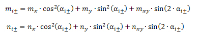
where
mi± - bending moment in the i-th direction of principal stress at lower (-) or upper (+) surface of 2D
ni± - normal force in the i-th direction of principal stress at lower (-) or upper (+) surface of 2D
The bold values in explanation of symbols can be presented in numerical output for check cracks
Recalculation reinforcement to direction of principal stresses
As was mentioned, there is possible to calculation crack width for user defined reinforcement and for total reinforcement. These reinforcements are adapted before recalculation to direction of principal stress.
Adaptation of user reinforcement
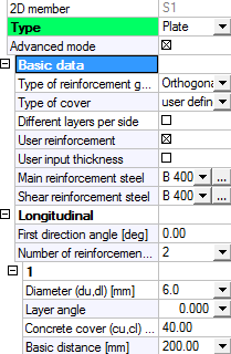
There are three possibilities for inputting user reinforcement to 2D member:
- via Reinforcement 2D
- via Free bars
- via concrete member data (the reinforcement it the same for whole 2D member)
| Reinforcement 2D | Free bars | Concrete member data |
|---|---|---|
|
|
|
|
|
|
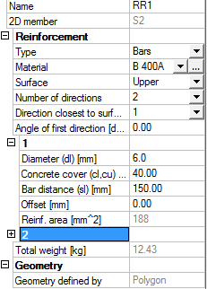
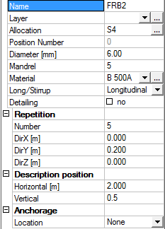
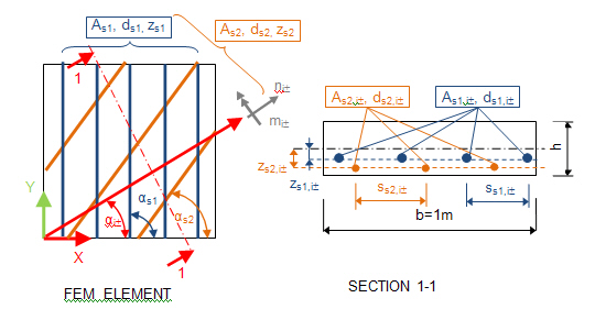
For calculation crack width it is necessary to know following parameters of user reinforcement:
- spacing between bars of reinforcement of k-th layer of user reinforcement (ss,user,k)
- area of reinforcement of k-th layer of user reinforcement (As,user,k)
- vertical position of k-th layer of user reinforcement measured from centre plane of FEM element (zs,user,k)
- diameter of bars of k-th layer of user reinforcement (ds,user,k)
- angle of bars of k-th layer of user reinforcement (αs,user,k) form x-axis LCS of FEM element in plane of FEM element
- quality of material of k-th layer of user reinforcement
If more layers of user reinforcement (Reinforcement 2D or Free bars) are defined in the same direction and vertical position, quality of material and diameter of reinforcement are the same, the one equivalent user reinforcement is created before recalculation of user reinforcement to direction of principal stress with the following parameters:
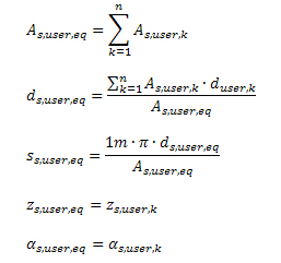
For example: Equivalent user layer of reinforcement is created if between bars of reinforcement mesh is inputted individual bars of reinforcement with the same diameter.
Adaptation of total reinforcement
Total reinforcement is SCIA Engineer is calculated for each direction of required reinforcement and for both surfaces of 2D member according to formula below
A_(s,tot,j±)=A_(s,add,j±)+A_(s,user,j±)
where
As,tot,j± - total area of reinforcement at upper(+) or lower surface(-) in j-th direction of required reinforcement
As,add,j - additional area of reinforcement at upper(+) or lower surface(-) in j-th direction of required reinforcement, which has to be added to user reinforcement
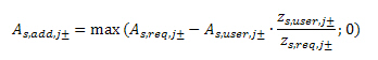
A_(s,add,j±)=max (A_(s,req,j±)-A_(s,user,j±);0)
As,user,j± - User (equivalent) reinforcement at upper(+) or lower surface(-) in j-th direction of required reinforcement defined via 2D reinforcement, free bars or defined in concrete member data recalculated to direction of required reinforcement
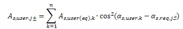
As,req,j± - Required reinforcement (reinforcement designed by the program) at upper(+) or lower surface(-) in j-th direction of required reinforcement
αs,req,j± - Directions of required reinforcement at upper(+) or lower surface(-) for j-th reinforcement defined in Design defaults or in concrete member data (if concrete member data is defined on 2D member)
Direction of required reinforcement (reinforcement designed by the program) can be set by user in concrete setup or in concrete member data (2 or 3 direction can be defined for each surface)
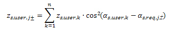
For recalculation user reinforcement to direction of required reinforcement, the resultant of vertical position of user reinforcement in j-th direction of required reinforcement is calculated according to formula
All types of reinforcement can be presented in services Member design ULS and Member design ULS+SLS (tree Concrete Advanced > 2D member), see [4]
The user reinforcement in these services is not taken into account for calculation total reinforcement, if:
- quality of material of required reinforcement and user reinforcement is different
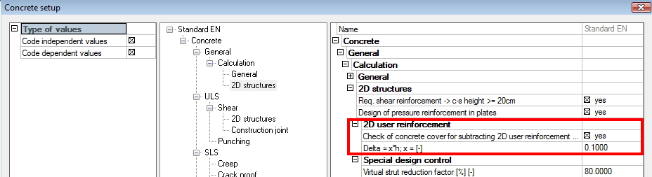
- the vertical position of user reinforcement and required reinforcement is greater than limit defined in concrete solver, it means if the condition below is not fulfilled
Abs(z_(s,user,j±)-z_(s,req,j±) )≤limit
and the check box for checking the vertical position is ON in concrete solver
where
z_(s,user,j±) - the resultant value of vertical position of user reinforcement at upper(+) or lower surface(-) in j-th direction of required reinforcement measured from centre plane of FEM element
z_(s,req,j±) - the vertical position of required reinforcement at upper(+) or lower surface(-) in j-th direction of required reinforcement measured from centre plane of FEM element
limit - limit value of distance between of user reinforcement and required reinforcement, which can be defined in Concrete solver > General >Calculation > 2D structures > group 2D user reinforcement
For calculation of crack width for total reinforcement the last designed area of total reinforcement in service Member design ULS or Member design ULS+SLS (tree Concrete Advanced > 2D member) is used. The layers of additional reinforcement in all directions of required reinforcement are added to user reinforcement and for these layers (user and additional reinforcement) is calculated crack width. Additional reinforcement calculated in service Member design ULS or Member design ULS+SLS is adapted before recalculation to direction of principal stresses to different position of user and required reinforcement was taken into account.
The additional reinforcement used for crack calculation can be different as additional reinforcement presented in service Member design ULS or Member design ULS+SLS, because different position of reinforcement is taken into account. The additional reinforcement presented in services for design and used for crack width will be same if position of user and required reinforcement are the same.
The additional reinforcement for crack width is not calculated, if quality of material of required reinforcement and user reinforcement is different
Limit value defined in Concrete solver > General >Calculation > 2D structures > group 2D user reinforcement is not checked for calculation additional reinforcement for check cracks, because different position are taken into account for calculation the additional reinforcement
The program finishes with error 516 (The crack width is not calculated because there are different quality of user and designed reinforcement) at check crack width, if material of user and additional reinforcement is not the same, see chapter 4
Recalculation of reinforcement to direction of principal stress
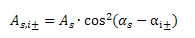
The adopted user reinforcement and calculated additional reinforcement for check cracks are recalculated to direction of principal stress according to formulas below:
area of one layer reinforcement (user or additional) in the i-th direction of principal stress at lower (-) or upper (+) surface of 2D
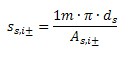
spacing between of one layer reinforcement (user or additional) in the i-th direction of principal stress at lower (-) or upper (+) surface of 2D
where
As - area of one layer of user (equivalent) reinforcement As,user(eq),k or calculated additional reinforcement A_(s,add,j±)
αs - angle of one layer of user (equivalent) reinforcement or additional reinforcement from x-axis of LCS of FEM element
ds - diameter of bars of one layer of user (equivalent) reinforcement or additional reinforcement
αi± - direction of principal stress at lower (-) or upper (+) surface of 2D from x-axis of LCS of FEM element
The vertical position and diameter of bars in the layer of user (equivalent) or additional reinforcement after recalculation to direction of principal stresses are not changed, it means
 and
and 
Check of normal stresses (occurring of crack width)
Before calculation crack width the normal concrete stresses on un-cracked section at the most tensioned fibber has to be checked. If condition below is satisfied, the crack width does not creates and the crack width is not calculated
where
σct,max,i± - normal concrete stress on un-cracked section at the most tensioned fibber of concrete cross-section in i-th direction of principal stress at lower (-) or upper (+) surface of 2D
ni± - recalculated value of normal force to the i-th direction of principal stress at lower (-) or upper (+) surface of 2D, see chapter 4.3
mi± - recalculated value of bending moment to the i-th direction of principal stress at lower (-) or upper (+) surface of 2D, see chapter 4.3
Ai,i± - cross-sectional area of transformed cross-section in the i-th direction of principal stress at lower (-) or upper (+) surface of 2D
Ii,i± - second moment of area of transformed cross-section in the i-th direction of principal stress at lower (-) or upper (+) surface of 2D
zt,max,i± - distance between centroid of transformed cross-section and the most tensioned fibber of concrete cross-section in the i-th direction of principal stress at lower (-) or upper (+) surface of 2D
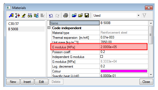
fct,eff - is the mean value of the tensile strength of the concrete effective at the time
when the crack may first be expected to occur. The value is loaded from material properties of concrete, see picture below
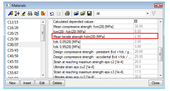
The value presented in material properties of concrete (picture above) is mean tensile strength of concrete in time 28 days. If cracking is expected earlier than 28 days, it is necessary input value fctm(t) in this time to material properties (EN 1992-1-1,clause 3.1.2(9))
The value of fctm,fl (EN 1992-1-1,clause 3.1.8(1)) can be input instead of value fctm, if restrained deformations such as shrinkage or temperature movements are taking into account for calculation crack width
Normal stress on un-cracked section at the most tensioned fibber for determination if crack width is occurred or not (check of normal stresses), should be calculated for characteristic combination of the load according to EN 1992-1-1, clause 7.2(2). There is made simplification in SCIA Engineer that this normal stress is calculated for the same type of combination as is used for calculation of crack width (load/combination/class inputted in service Crack control, see chapter 3.2.1)
EN 1992-1-1 does not give instruction, how creep under varying load should be taken into account for calculation of the crack width. The creep can be generally be taken into account by assuming that effective module of elasticity (EN 1992-1-1, clause 5.8.7(2) ) for calculation modular ratio (Es/Ec,eff 15). A Lower value of modular ratio (greater value of module of elasticity of concrete than effective ) may be used where less than 50 % of the stresses arise from quasi-permanent load. There are two possibilities for changes module of elasticity:
- The effective module of elasticity have to input directly to material properties, see picture below
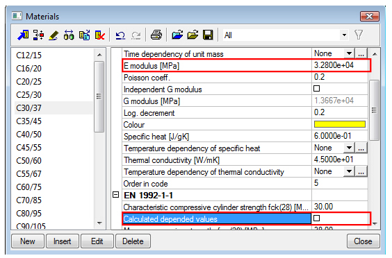
- The model Construction stages with type E modulus function is used, where the function of effective module of elasticity is inputted in time, see [3]
There is possible to present cracking forces (ncr, mcr) in numerical output for crack control. This cracking forces are forces which caused reaching of value fc,teff (occurring of crack width in cross-section) in the most tensioned fibber of concrete cross-section in direction of first or second principal stress. For calculation of this cracking forces is used condition, that eccentricity of inputted forces and cracking forces has to be same.
Calculation crack width in direction of principal stresses
As was mentioned, crack width is calculated in direction of principal stresses at upper and lower surface, it follows 4 times in one FEM element. The crack width is calculated only in case that normal concrete stresses on un-cracked section at the most tensioned fibber is greater than effective tensile strength of the concrete, see chapter 4.5. In other cases calculation finishes with warning 12, see chapter 4
| Value | Upper surface | Lower surface | ||
|---|---|---|---|---|
| Principal angle | α1+ | α2+ | α1- | α2- |
| Normal force | n1+ | n2+ | n1- | n2- |
| Moment | m1+ | m2+ | m1- | m x2 |
| Crack width | w1+ | w2+ | w1- | w2- |
The crack width is calculated according to EN 1992-1-1, formula 7.8.
w_(i±)=s_(〖r,max〗_(i±) )∙〖(ε_sm-ε_cm)〗_(i±)
where
sr,max,i± - maximum crack spacing in the i-th direction of principal stress at lower (-) or upper (+) surface of 2D member
(εsm - εcm)i± - difference between mean strain in the reinforcement and the mean strain in concrete between the cracks in the i-th direction of principal stress at lower (-) or upper (+) surface of 2D member
The bold values in explanation of symbols can be presented in numerical output for check cracks
Calculation mean strain in the reinforcement and concrete
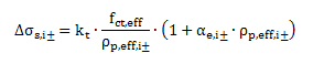
Difference between mean strain in the reinforcement and the mean strain in concrete between the cracks is calculated according to EN 1992-1-1, formula 7.9
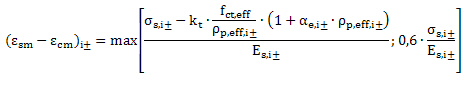
where
σs,i± - the stress in the most tensioned reinforcement ( reinforcement the nearest to the most tensioned edge of 2D member) in the i-th direction of principal stress at lower (-) or upper (+) surface of 2D member
Es,i± - design value modulus of elasticity of the most tensioned reinforcement ( reinforcement the nearest to the most tensioned edge of 2D member) in the i-th direction of principal stress at lower (-) or upper (+) surface of 2D member
kt - factor dependent on duration of the load. The value can be set in Concrete solver > SLS > Crack proof > group General.
fct,eff - is the mean value of the tensile strength of the concrete effective at the time
when the cracks may first be expected to occur. The value is loaded from material properties of concrete, see notes in chapter 4.5
ρp,eff,i± - ratio of reinforcement within effective area of concrete in tension in the i-th direction of principal stress at lower (-) or upper (+) surface of 2D member
αe i± - ratio of design value of modulus of elasticity of the most tensioned reinforcement and modulus elasticity of the concrete in the i-th direction of principal stress at lower (-) or upper (+) surface of 2D member
The bold values in explanation of symbols can be presented in numerical output for check cracks
From the formula above follows, that difference between mean strain in the reinforcement and concrete mainly depends on:
strain (stress) in the most tensioned reinforcement,
effect of tension stiffening.
Strain in the most tensioned reinforcement
Strain in the most tensioned reinforcement is calculated according to formula below

There are used following preconditions in SCIA Engineer:
- The section is loaded by load/combination/class selected in service crack control, see chapter 3.2.1
- Transformed section is used
- Plane section remains plane after loading (deformation) too
- Tensile strength of concrete is not taken into account (cracked section)
- ideal bond between concrete and reinforcement is taken into account, it means change strain of reinforcement εs and concrete fibber εc in the same position is the same
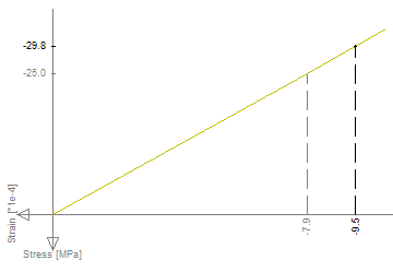
- The linear strain-stress diagram of concrete and reinforcement with infinite branch is used, it means, that distribution of stress is linear and depends on change of strain (Hooke’s law)
Linear stress-strain diagram of concrete:
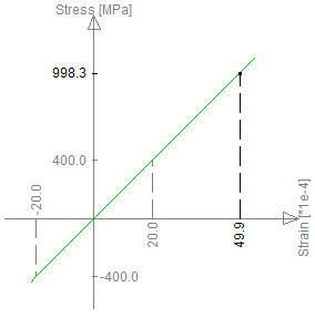
Linear stress-strain diagram of reinforcement:
The program finishes with error 583 (Forces are zero or no equilibrium is found), if equilibrium on the cracked section, with taking into account conditions above, is not found (chapter 4)
Effect of tension stiffening
The tension stiffening effect represents the capacity of the intact concrete between neighbouring cracks to cany a limited amount of tensile forces. The reason for this effect is bond slip between the reinforcement and the neighbouring concrete. The decreasing of stress in reinforcement due to tension stiffening can be calculated according to formula:
The change of stresses depends on:
- factor dependent on duration of the load (kt),
- the mean value of the tensile strength of the concrete (fct,eff),
- ratio of reinforcement within effective area of concrete in tension (ρp,eff,i±),
- ratio of design value of modulus of elasticity (αe i±).
Factor dependent on duration of the load (kt)
This value can be set in Concrete solver > SLS > Crack proof > group General. The following values should be used according to code EN 1992-1-1, chapter 7.3.4(2):
- kt = 0,6 for short term loading
- kt = 0,4 for long term loading
the value kt = 0,6 for long term loading in SCIA Engineer should be used:
- for permanent or long-term loadcases
- for quasi permanent combination
- for other SLS combinations, which predominate long term loading in
the value kt = 0,4 for short term loading in SCIA Engineer should be used:
- for variable or short-term load cases
- for other SLS combinations, which predominate short term loading in
the effect of tension stiffening will not be taken into account, if zero value is defined for value kt,
The mean value of the tensile strength of the concrete (fct,eff)
It is the mean value of the tensile strength of the concrete effective at the time when the cracks may first be expected to occur. The value is loaded from material properties of concrete.
The value presented in material properties of concrete is mean tensile strength of concrete in time 28 days. If cracking is expected earlier than 28 days, it is necessary input value fctm(t) in this time to material properties (EN 1992-1-1,clause 3.1.2(9))
The value of fctm,fl (EN 1992-1-1,clause 3.1.8(1)) can be input instead of value fctm, if restrained deformations such as shrinkage or temperature movements are taking into account for calculation crack width
Ratio of reinforcement within effective area of concrete in tension (ρp,eff,i±)
This ratio of reinforcement is calculated only for non-prestressed reinforcement (prestressed reinforcement is not taken into account for check crack width) according to formula
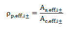
As,eff,i± - area of non-prestressed reinforcement (see chapter 4.4) within effective area of concrete in tension in the i-th direction of principal stress at lower (-) or upper (+) surface of 2D member
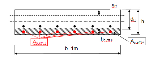
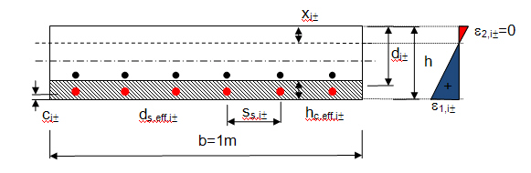
Ac,eff,i± - the effective area of concrete in tension surrounding the reinforcement in the i-th direction of principal stress at lower (-) or upper (+) surface of 2D member. For 2D member this area can be calculated according to formula: Ac,eff = hc,eff.1m
hc,eff,i± - the depth of effective area of concrete in tension surrounding the reinforcement in the i-th direction of principal stress at lower (-) or upper (+) surface of 2D member.
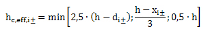
h thickness of 2D member (thickness of FEM element in centroid)
di± - effective depth of 2D member calculated in centroid of FEM element in the i-the direction of principal stress at lower (-) or upper (+) surface of 2D member.
xi,± - depth of concrete in compression calculated for uncracked section.
The program finishes with error 514 (The crack is not calculated, because there is no reinforcement within the effective area of concrete in tension), if area of non-prestressed reinforcement As,eff,i is zero, see chapter 4
The bold values in explanation of symbols can be presented in numerical output for check cracks
Ratio of design value of modulus of elasticity (αe i±)
Ratio of design value of modulus of elasticity is calculated according to formula:
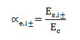
Es,i± - design value of modulus of elasticity of the most tensioned reinforcement ( reinforcement the nearest to more tension edge of 2D member) in the i-th direction of principal stresses at lower (-) or upper (+) surface of 2D member. The value is loaded from material properties of the reinforcement, see picture below
Ec - modulus of elasticity of concrete. The value is loaded from material properties of the concrete
The creep for calculation crack width can be generally taken into account by assuming that effective module of elasticity (EN 1992-1-1, clause 5.8.7(2) ) is used for calculation modular ratio (Es/Ec,eff ≤ 15). A Lower value of modular ratio (greater value of module of elasticity of concrete than effective value ) may be used where less than 50 % of the stresses arise from quasi-permanent load. There are two possibilities for changes module of elasticity:
- The effective module of elasticity have to input directly to material properties
- The model Construction stages with type E modulus function is used, where the function of effective module of elasticity is inputted in time, see [3]
Calculation maximum crack spacing
Maximum crack spacing is calculated according to EN 1992-1-1, clause 7.3.4(3) .Clause 7.3.4(4) is not taken into account for calculation maximum crack spacing in SCIA Engineer.
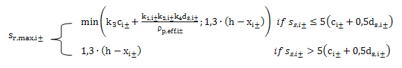
where
k3, k4 - coefficients of calculation loaded from national annex setting (Manager of national annex >code EN 1992-1-1 > SLS)
c,i± - cover of the most tensioned reinforcement ( reinforcement the nearest to more tension edge of 2D member ) by the concrete in the i-th direction of principal stress at lower (-) or upper (+) surface of 2D member
k1,i± - coefficient which takes account of the bond properties of the bonded reinforcement in the i-th direction of principal stress at lower (-) or upper (+) surface of 2D member
- k1,i± = 0,8 for high bond bars (in SCIA Engineer bar surface = ribbed)
- k1,i± = 1,6 for bars with an effectively plain surface e.g. prestressing tendons (in SCIA Engineer bar surface = smooth)
The bar surface can be defined in material properties of the reinforcement
k2,i± - coefficient which takes account of the distribution of strain in the i-th direction of principal stress at lower (-) or upper (+) surface of 2D member
- k2,i± = 0,5 for pure bending
- k2,i± = 1,0 for pure tension
- k2,i± = (ε1,i± + ε2,i±)/2•ε1,i±
ε1,i± - the greater tensile strain at the boundaries (edges) of the cross-section in the i-th direction of principal stress at lower (-) or upper (+) surface of 2D member. The strain is calculated for uncracked section with taking into account conditions in chapter 4.6.1.1 and the value of strain is zero for edge in compression
ε2,i± - the lesser tensile strain at the boundaries (edges) of the cross-section in the i-th direction of principal stress at lower (-) or upper (+) surface of 2D member. The strain is calculated for uncracked section with taking into account conditions in chapter 4.6.1.1 and the value of strain is zero for edge in compression
ρp,eff,i± - ratio of reinforcement within effective area of concrete in tension in the i-th direction of principal stress at lower (-) or upper (+) surface of 2D member
αe i± - ratio of design value of modulus of elasticity of most tensioned reinforcement and modulus elasticity of the concrete in the i-th direction of principal stress at lower (-) or upper (+) surface of 2D member
xi,± - is depth of concrete in compression calculated for uncracked section with taking into account conditions in chapter 4.6.1.1.
h - thickness of 2D member (thickness of FEM element in centroid)
ss,i± - centre to centre spacing between bars of reinforcement of the most tensioned layer of reinforcement in the i-th direction of principal stress at lower (-) or upper (+) surface of 2D.
If the angle between most tensioned reinforcement and i-th direction of principal stress is lesser than 15 degree, centre to centre spacing of most tensioned reinforcement is taken into account, which is calculated according to formula below, see chapter 4.4.3
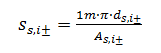
If the angle between most tensioned reinforcement and i-th direction of principal stress is equal or greater than 15 degree, average value of centre to centre spacing calculated from all tensioned layers is taken into account, which is calculated according to formula below ( clause 7.3.4(4) in EN 1992-1-1)
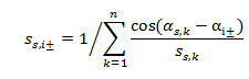
ds,i± - diameter of bars of the most tensioned layer of reinforcement in the i-th direction of principal stresses at lower (-) or upper (+) surface of 2D, see chapter 4.4.3
The bold values in explanation of symbols can be presented in numerical output for check cracks
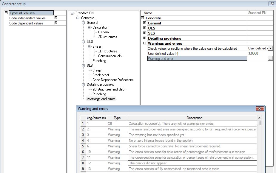
Warning and errors for check cracks of 2D member
The following warnings and errors may be occurred during the check crack width of 2D member
| Number | Type | Explanation | Description/Solution |
|---|---|---|---|
| 12 | Warning | The crack did not appear | Normal concrete stress on un-cracked section at the most tension fibber of concrete is lesser than the mean value of the tensile strength of the concrete. It means that inputted forces in the i-th direction of principal stress (m,n) are lesser than cracking forces (mcr, ncr) |
| 514 | Error | The crack is not calculated, because there is no reinforcement within the effective area of concrete in tension | It is necessary to input layer of reinforcement to effective area of the concrete or decrease concrete cover of inputted reinforcement, see chapter 4.6.1.2 |
| 516 | Error | The crack width is not calculated because there are different quality of user and designed reinforcement |
The different material of user and designed reinforcement is not supported (chapter 4.4.2) and therefore it is necessary:
|
| 567 | Error | No reinforcement found in the cross-section |
The area of reinforcement is missing for check crack width (chapter 2.2.1) If Type of used reinforcement = As,tot in service crack control is selected, then area of reinforcement has to be designed in service Member design ULS or Member design ULS+SLS. If Type of used reinforcement = As,user in service crack control is selected, then user reinforcement has to be inputted to 2D member |
| 583 | Error | Forces are zero or no equilibrium found |
The strain (stress) in the most tensioned reinforcement was not calculated (see chapter 4.6.1.1) and it is necessary to: |
| 614 | Error | The limit crack was exceeded |
The calculated value of crack width is greater than limit value of crack width. It is necessary to
|
Explanation of errors and warning can be presented:
- In numerical output via check box Print explanation of errors and warnings in service for crack control, see chapter 3.2.1
- In dialog Calculation info via action button Calculation info in service for crack control, see chapter 3.2.1
- In dialog Warnings and errors (Concrete solver > Concrete > Warning and errors >)
Abbreviation
Literature
[1] EN 1992-1-1: 2004 Eurocode 2 : design of concrete structures – Part 1: General rules and rules for building
[2] ENV 1992-1-1: 1991 Eurocode 2 : design of concrete structures – Part 1: General rules and rules for building
[3] Manual Constructions Stages, TDA, Prestressing, manual for SCIA Engineer
[4] 2D concrete design- EN 1992-1-1, tutorial for SCIA Engineer