3D Wind-Load Generator
The 3D Wind-Load Generator is a complex tool for generation of wind load acting against buildings. The module is available for the following codes: EC-EN (Eurocode) and IBC (International Building Code). Module of Eurocode includes calculation of external pressure coefficients by their national annexes for following countries: Austria, France, Belgium, Germany, Netherlands, Slovakia and UK.
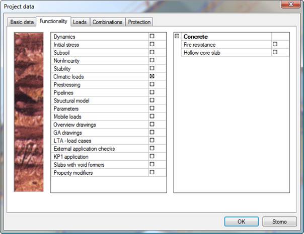
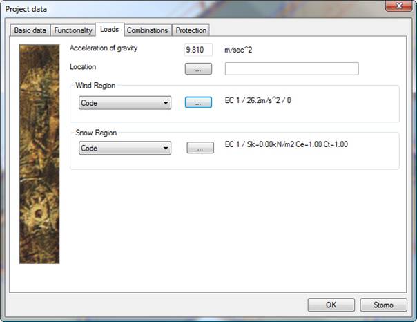
Project settings
In the Project data dialogue, functionality Climatic load must be selected. In addition, the code for the wind loads must be selected.
DATA for calculation
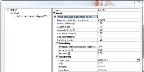
In Setup manager for wind can be set which pressure coefficient will be used.
For all NA:
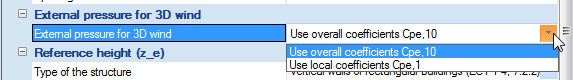
Selected pressure coefficient is always used for all zones. It not possible to mix them in one project.
For Austrian NA:
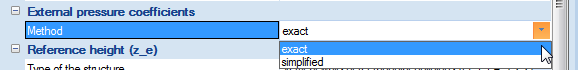
Exact method includes tables 3 and 4 for vertical walls and all zones for roofs from Austrian NA.
Simplified method includes table 6 and zone reduction for roofs in case that area of zones F and G is less than 20% of entire roof area.
For Standard EN (and those which it used because they are not implemented yet), Belgian NBN-EN NA, British BS-EN NA, Dutch NEN-EN NA, Finnish SFS-EN NA, French NF-EN NA, Slovakian STN-EN NA and Czech CSN-EN NA:
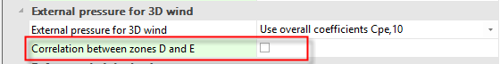
If Correlation between zones D and E is ON the Note from EN 1991-1-4:2005 chapter 7.2.2(3) is applied. I.e. the lack of correlation of wind pressures between the windward and leeward side is considered as:
- For buildings with h/d ≥ 5 the resulting force is multiplied by 1.
- For buildings with h/d ≤ 1, the resulting force is multiplied by 0,85.
- For intermediate values of h/d, linear interpolation is applied.
For IBC:
Necessary to select Calculation method - All heights or Low-rise for ASCE 7-05, Directional or Envelope for ASCE 7-10. It says which wind pressure curve is used.
Note: For Directional procedure in 3D wind generator a variable wind pressure is automatically applied on windward walls and a constant one on others.
Definition of the outer surface of the building
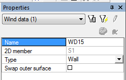
Prior the load can be generated it is necessary to select (mark) those 2D members in the model of the structure that are supposed to form the outer surface of the building. 2D members of type plate or (flat) wall have property called 3D wind. If this property is set to ON, the 2D member is taken into account by the wind load generator.
The property 3D wind is available for slabs and flat walls and for panels. It is not available during the input of the member but only after. If ON, blue contour (Wind data) is displayed on the member.
The outer surface of the 2D member can be selected using parameter Switch outer surface. This switch is useful as the direction of the wind is defined in the local coordinate system of the 2D member.
Generation and editing of zones
Once the 3D wind property is set to ON in the property dialogue of the member, entity called “wind data” is automatically generated on the 2D member. This “wind data” entity collects all the wind information.
2D members with the 3D wind property set ON must form a closed “block”. If the outer surface of the building is not closed or if an interior 2D member has the 3D wind property set to ON, the wind load cannot be automatically calculated.
The Wind data entity can be of either of Wall, Roof, Parapet or Free-standing wall type. At least one roof member must be defined in the project in a case that standard walls are defined.
The roof types available are:
- flat
- monopitch
- duopitch
- hipped
For ASCE7-10 Envelope procedure new items are in wind data properties:
Wall wind data
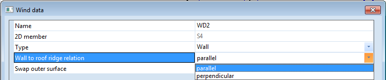
Wall to roof ridge relation - defines if wind zones have to be generated for a wall oriented parallel or perpendicular to roof ridge.
Roof wind data
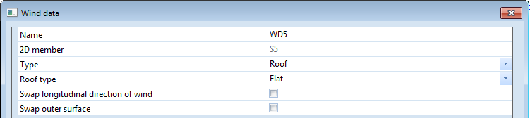
Swap longitudinal direction of wind - only for flat roofs; defines how wind zones have to be generated on flat roof. Default values is OFF, i.e. the ridge is considered parallel with global Y axis.
Zones
The load the structure is subject to is, following the regulations of the appropriate code, divided to zones according the arrangement of the structure. This division is saved for every wind direction and it can be either automatically generated or, if required, input or edited manually.
This is done in the Zones editor. The editor can be opened from the Wind data property dialogue using action button [Edit zones].
Zones editor
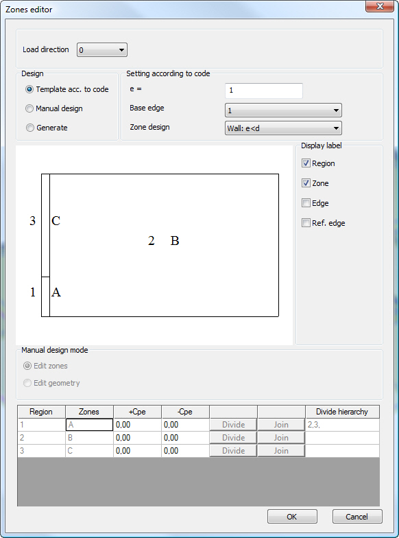
There are three modes for editing of zones.
Template acc. to code
This option enables the user to divide the geometry to zones according to templates based on the appropriate code. The user must input the value of e, select the Base edge and Zone design. The values of Cpe coefficient are predefined by the program and can be adjusted manually.
For projects with EC-EN code selected, we refer to EN 1991-1-4:2005(E), Chapter 7 for more information.
For IBC code, the Template option is not available.
Manual design
In this mode all the values are defined manually by the user.
If the Manual design mode is activated after the Template mode, all the values in the dialogue remain AS IS and the user can modify them as required.
However, if the Manual design mode is activated after the automatic Generate mode, all the values are deleted and the user must define everything from scratch.
Individual zones can be divided or merged using buttons Divide and Join. When a zone is divided there are three types of dividing available:
- Parallel = the “cut” goes along the selected edge.
- Horizontal = the “cut” goes horizontally
- Vertical = the “cut” is vertical
Generated zones
In this mode the zones and values of Cpe coefficient are calculated automatically by the program. If the user swaps from the Generate option to another one, the zones are deleted.
Note: For direction 45° and closed values, load is generated only on parapets and free-standing walls and nothing on standard walls and roofs.
Load Case
Load cases can be generated automatically using the defined criteria or defined manually.
Automatic generation of load cases
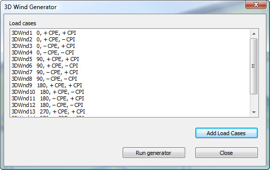
Load cases can be defined using function 3D wind generator in the Load service. On first opening the list of wind load cases is empty. The program can generate required load cases after the criteria are specified. To do so, click button Add load cases to open the dialogue where these criteria can be input.
The user defines the wind direction and selects which “plus”+”minus” combination of Cpe/Cpi coefficients is to be used. Also the value of the Cpi coefficient is input here (manually).
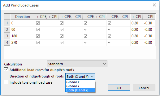
In that case the option Additional load cases for duopitch roofs is ON, at θ = 0° on the windward face around a pitch angle of α = -5° to +45° four cases for duopitch roofs are considered where the largest or smallest values of all areas F, G and H are combined with the largest or smallest values in areas I and J.
Note 1: Load case description begins with +/-Cpe or -/+Cpe. It defines on which part of the duopitch roof is used positive and negative Cpe. The order of signs is taken from the left to right side for each direction.
Note 2: Description explanation, e.g. 90, +/-CPE, + CPE, + CPI i.e. direction 90° / for duopitch roofs with ridge/trough along global axis X on windward part of roof +Cpe is used and on leeward part of the roof -Cpe is used / for all other roofs +Cpe is used / +Cpi is used for the load case.
To reduce the number of generated load cases the user can define if the ridge/trough of duopitch roof is in one or both directions. It is specified in combo box Direction of ridge/trough of roofs - Global X (additional load cases are generated only for 90° and 270°), Global Y (additional load cases are generated only for 0° and 180°), Both (X + Y) (additional load cases are generated for all directions).
Note: There is a check for the angle of the windward part of roof. If there is set that additional load cases have to be generated but no duopitch roof with angle of α = -5° to +45° exists, load cases are generated but they remain empty after the 3D wind load generation. It prevent to get duplicate load cases and spent time during analysis on it.
On closing the Add wind load cases dialogue the load cases are generated.
Note: For ASCE 7- 10 Envelope procedure no -Cpe exists therefore only 8 load cases are generated.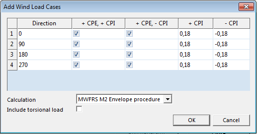
Manual input of load cases
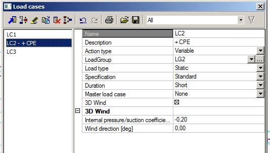
When the wind load case is input manually, item Description MUST contain text either “+ CPE” or “- CPE” written in upper case with one space character between the sign and the text “CPE”.
This defines which Cpe coefficient will be used. The +/-Cpi coefficient and direction are taken in account from the group 3D Wind.
Generation of load cases
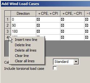
When the “Add load cases” in the main dialogue is clicked, the main dialogue shows settings for the generation of load cases for individual directions. For each direction, any sign combination of Cpe and Cpi coefficients can be defined. Directions 0,90,180,270 are predefined. If you want to add another – use the right mouse button click to activate the menu – see below.
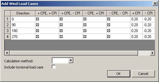
Calculation Metod
For EC only method “Standard” is available.
For IBC there is “MWFRS M2 Low-rise” and "MWFRS M2 All height" method for ASCE 7-05 or "MWFRS M2 Envelope procedure" and "MWFRS M2 Directional procedure" for ASCE 7-10 (see the IBC code for details).
Include torsional load case
This checkbox is available only for the IBC code (see the IBC code for details).
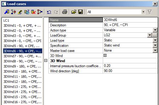
Manual definition of a 3D wind load case
In the properties of a variable load case you can select option “3D wind”. When the option is ticked, new properties relating to the wind load are added to the property dialogue. This load case is later user to store the generated load.
Direction – wind load direction in GCS
Internal pressure/suction coefficient – value of Cpi coefficient (see the appropriate code for details)
The 3D wind option is available only for Action type = Variable.
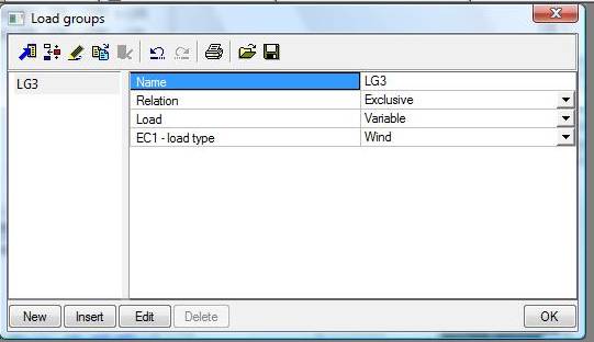
Load group
Generation of load
The load is generated only to load cases of “3D wind” type. The generated load is of “3D wind” type. The value is set to the generated or manually input value of the Cpe coefficient. The geometry of the load is defined by the arrangement of wind zones across the 2D element.
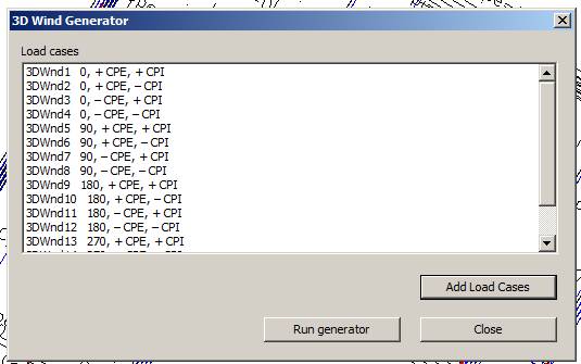
Run generator button
It runs the Wind Load Engine that calculates wind zones according to the appropriate code and calculates the load values.
After successful calculation a message box is shown.
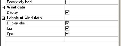
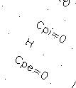
View flags
Cpi, Cpe labels and the name of the zone is displayed using the settings from Palette settings > Screen > Font > item Slab.
In the View parameters Setup dialogue, you can control what is displayed on tab Loads/masses.