Introduction to free loads
Free load is related to slabs. The load is not defined by the entity it acts on, but by a specific load border. Free loads are defined by means of "loading entities" that may overlap or affect one or more slabs.
Available types of "loading entity"
|
The loading entity is defined by means of a general polygon. |
|
|
line |
The loading entity is defined by means of a line or polyline. |
|
point |
The loading entity is defined by means of a point. |
Note: The loading entity may be oriented arbitrarily but can be input only in the XY plane of the current UCS. Therefore, before one can input the free load, it is necessary to adjust the working plane accordingly.
Each loading entity keeps a record of what was the orientation of the UCS when the entity was defined. The orientation of the UCS is important as some of the loading parameters may be related to this UCS. Whenever any already defined free load entity is selected, the appropriate UCS is activated.
If an inclined slab is subject to free load (the word inclined means that the plane of the slab and the loading plane of the loading entity are not parallel), the final load value is calculated from the projection of defined load onto the selected slab.
Free load is independent of finite element mesh and possible refinement or "coursing" of the mesh does not affect the calculated results.
It is possible to manually define which particular slabs should be subject to a particular free load. Alternatively, the program may automatically detect all affected slabs and apply the load on them. The former approach enables the user to extract specific slabs from the effect of the defined load.
Validity of free loads
The validity of free load means (i) which particular slabs are subject to the given load and (ii) the halfspace where the load acts (i.e. the direction of the load).
|
All |
Both entities located under and above the defined load are subject to the defined load. |
|
-Z |
If ON, the load is supposed to act only in the space located along the negative half of Z-axis of the User coordinate system. That means that ONLY the entities located UNDER the XY-plane of the UCS are subject to the load in question. |
|
-Z (incl. 0) |
The same as above plus entities located IN the XY-plane of the UCS. |
|
Z = 0 |
Only the entities located in the XY-plane of the UCS are subject to the load in question. |
|
+Z |
If ON, the load is supposed to act only in the space located along the positive half of Z-axis of the User coordinate system. That means that ONLY the entities located ABOVE the XY-plane of the UCS are subject to the load in question. |
|
+Z (incl. 0) |
The same as above plus entities located IN the XY-plane of the UCS. |
|
Selected |
The user must define which particular entities are supposed to be subject to the given load. |
The validity parameters can become more clear from the following example.
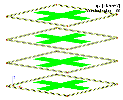
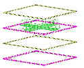
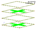
Let’s have four slabs input one above the other. Define free area load in the plane of the third slab (from the bottom).
First, set option Select to All and validity to All. Perform the calculation and open function Calculation, mesh > 2D data viewer > Surface load. You can see that the load acts on all four slabs.
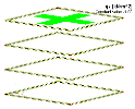
Second, set option Select to All and validity to Z. The load acts only on the top slab because it acts only on that part of the structure that is above the plane in which the load is defined. (If the load was input let’s say 5 cm below the midplane of the third (from bottom) slab, also that slab would be subject to the load.)
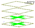
Third, set option Select to All and validity to –Z. The load acts only on two bottom slabs because it acts only on that part of the structure that is below the plane in which the load is defined.
Fourth, set option Select to Select and validity to All. Select the most bottom slab and the third one.
The load acts only on the two selected slabs only.
Note: Attention must be paid to the situation when parameter Select is set to Select and parameter Validity is set to Z or –Z. In this case the two conditions are combined to make a product. So it could happen that there is no slab that would comply with both the conditions: being selected and being in the proper semi-space.
Note: The loads generated from a defined free load can be neither moved nor copied. Functions Move AddData and Copy AddData are disabled for them.
Examples of free load behaviour in special cases
In this chapter, few examples of the free load behaviour are described. For all the examples listed here, the property "Validity" of the discussed free load (of all the free load types - point force, line force, moment) was set to "All", and the property "Select" was set to "Automatic". These examples are provided, so the user is aware of the way the free load is generated in some special cases, when the automatic selection has been chosen. Free loads behaviour are described with the focus on their combination with load panels . The property "Panel type" in these examples has been set as "To panel edges and beams" (more info here). The property "Load transfer method" was set as "Accurate (FEM), hinged link with beams". Actually, it does not matter whether with "hinged" or "fixed" link with the beams now (or the "Load transfer method" could have been also "Standard"), as in these examples, the assignment of the generated load to certain panels is discussed, rather then the exact distribution and the generated values.
Note: The load transfer method "Tributary area" is not supported in combination with free loads.
Example 1 - free load exactly on (or under) the edge of several load panels
Geometry description:
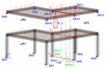
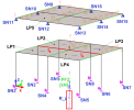
The free point force no. 1 (FPF1, 1 kN) and the free line force no. 1 (FLF1, 1 kN/m on 1 m length) are both located on the line l1(red dashed line). Lines l1, l2 and l3 are exactly under each other (in the same plane). Line l3 is identical with the edges of the load panel no. 2 (LP2) and load panel no. 3 (LP3). Load panel no. 1 (LP1) is however continuous, it is not divided into two load panels by line l2.
Load panel set up: The property "Panel type" is set "To panel edges and beams", and the property "Load transfer method" as "Accurate (FEM), hinged link with beams".
Free load set up: For both, FPF1 and FLF1, the property "Validity" is set as "All", and "Select" as "Auto".
Expected behaviour:
Forces from FPF1 and also FLF1 are generated on all the load panels, LP1, LP2 and LP3. Therefore, in the "upper floor" (LP2 and LP3), the force from FPF1 is applied twice in the summary, as well as FLF1 - both on LP2 and also LP3, because both free loads are located exactly under the load panel edge. See the reaction resultant in the z direction, R_z, which is summarized from the nodal supports SN8 - SN14. The value is equal to 4 kN. If this duplication of the generated forces is not desired by the user, one load panel needs to be used - LP1 (of an "L" shape from the top view). The resultant reaction in the z direction of the nodal supports SN1 - SN7 would be 2 kN in this case (1 kN from FPF1, and 1 kN from FLF1).
Note: The free point moment works analogically.
Example 2 - free load exactly on (or under) the intersection of several load panels
Geometry description:
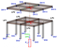
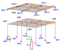
The free point force no. 2 (FPF2, 1kN) is located exactly under the points P1 and P2, which are on intersections of the corresponding red dashed lines (see the figure above). In the bottom floor, the point P1 is located in the intersection of the load panels LP1 - LP4. In the upper floor there is only one load panel LP5.
Load panel set up: The property "Panel type" is set "To panel edges and beams", and the property "Load transfer method" as "Accurate (FEM), hinged link with beams".
Free load set up: the property "Validity" is set as "All", and "Select" as "Auto".
Expected behaviour:
Forces from FPF2 are generated on all the load panels, LP1 - LP5. Therefore, on the "bottom floor" (LP1 - LP4), the force from FPF2 is generated 4 times (once per each of four load panels). Reaction resultant in the z direction, R_z, which is summarized from the nodal supports SN1 - SN8 is 4 kN. If this duplication of the generated forces is not desired by the user, one load panel needs to be used - LP5. The resultant reaction in the z direction of the nodal supports SN9 - SN16 would be 1 kN in this case.
Note: The free point moment works analogically.
Example 3 - generated line load - slightly shifted position of the free load
Geometry description:
This is the same case as the "example 2", the only difference is, that the location of the FPF2 has been shifted by a little number (1 mm) in both, x and y direction of the global coordinate system (GCS). In both cases in a positive direction of the GCS system axes.
Expected behaviour:
In the bottom floor, the load generated from the FPF2 is now applied only on the LP3. The load panels LP1 - LP4 are each separate (divided by the green lines and red dashed lines l4 and l5). Therefore, there is no generated load on LP1, LP2 and LP4. The reaction resultant in the z direction, R_z, which is summarized from the nodal supports SN1 - SN8 is now only 1 kN. In case of the "upper floor" with one continuous load panel LP5, the difference between this case and the previous second example is rather negligible.
The only inconvenience here is the fact, there are triangular line loads generated based on the point force. These generated line loads are applied on a longer line length, therefore changing the nature of the point force, if this point force is located close to a load bearing member (beam).
Note: The free point moment works analogically.
Example 4 - generated line load - finer mesh size of the load panel
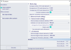
In order to decrease the length of the line on which the triangular line load is generated, in case this is desired, the mesh size of the load panel needs to be finer. In the advanced mesh setting, decrease the value of "Average size of panel element". For example form the default "1 m" to "0.25 m", as in the figure below.
Geometry description:
Exactly the same as in the previous "example 3", the only difference is in the finer mesh for load panels.
Expected behaviour:
The line length on which the triangular line load has been generated is now significantly smaller. The nature of the generated load from the free point force FPF2, which is very close (considering its projection to the corresponding plane of load panel) to some load bearing element (beam in this case) is described in more suitable way (generated load resembles the effects of the point force closely). This might be desired for some positions of free point forces.
Note: If the projection of the FPF2 would be somewhere near the middle of the load panel LP3, finer load panel mesh would not have such a big influence as in the example described above.
Example 5 - free load exactly under the slab edges or under the line hinge
Geometry description:
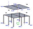
The free point force no. 3 (FPF3, 1 kN) is located exactly under the edge between the slab S1 and S2, and also under the edge between slabs S3 and S4. There is a line hinge LH1 on the edge between S3 and S4. LH1 belongs to the edge of the slab S4. The released degrees of freedom for LH1 are uz and fix. The mesh size of the 2D elements is 0.5 m.
Free load set up: property "Validity" is set as "All", and property "Select" as "Auto".
Expected behaviour:
For the slabs S1 and S2, there is a continuous mesh generated through both the slabs. The slabs are connected, as if there was one slab. Load applied on these slabs S1 and S2 is one generated point force. The resultant of the reactions from the nodal supports SN1 - SN8 is 1 kN.
In case of the upper floor slabs, S3 and S4, the presence of the line hinge LH1 makes these two meshes (of slab S3 and S4) separate. The line hinge itself is defined as a contact between these two edges (more precisely nodes on two edge lines). In this case, the generated free load is applied only on one of these slabs (the one with the prior number of mesh elements). In the example case, the load is applied on the slab S3 - see the reactions (in z direction) of the line supports SLE1 and SLE2 in the figure above. There are no reactions in the SLE3 and SLE4. The determination, to which of these slabs the generated force load is applied, does not depend on the line hinge LH1 assignment (whether assigned to the edge of slab S3 or S4).
Note: The result is the same also if there were line hinges of the same type (releasing uz and fix) on the both edges of the slab S3 and S4.
Note: In cases like this, when the free point force (or analogically free line force, or free point moment) is located exactly under such line hinge between two slabs, the user should be aware of the fact, on which of these slabs is the generated load applied. It is recommended user checks this carefully. A little shift as described in example 3 might be defined.
Note: In case of the free load (point force, point moment, line force) located under the edge of load panels, the load is generated on both of these load panels, because there are two edges, one of each panel (internal panel meshes are not continuous, but separate). Load panels are not structural elements. However, slabs are structural elements, and the finite element mesh of the two slabs with one joint edge is continuous by default. In case of the line hinge presence, the load is also applied only to one of these slabs.

