Connection forces - input / forces
The Connection forces command serves for displaying connection forces in ends of 1D members connected to selected node in structure. As prerequisity it is necessary to define this node in functionality Connection input
Usage
- Calculate a FEM analysis of the model
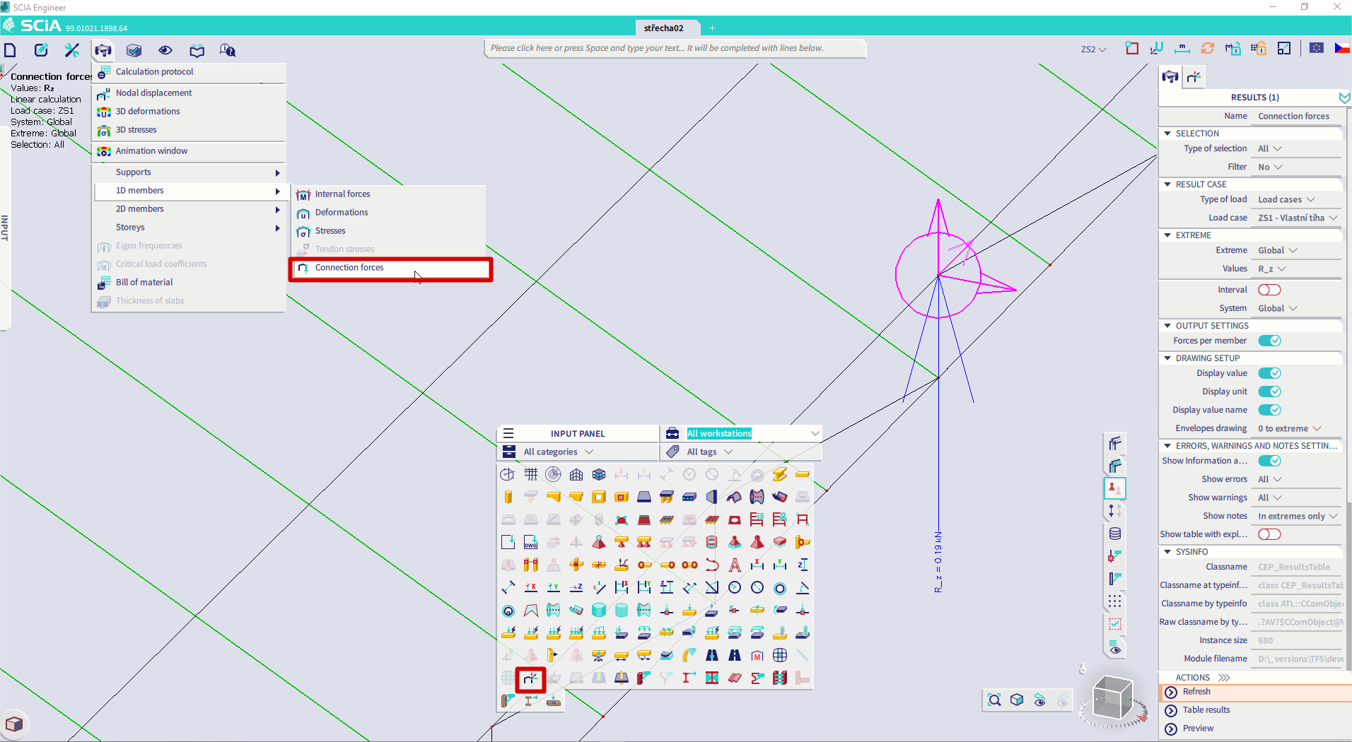
- Go to Input panel > Connection forces - input
- Define node of interest and other parameters of connection.
- Select this Connection input entity.
- Go to Results > 1D members > Connection forces
- Set properties of the command to specify mainly:
- Click on [Refresh] action button to display the results
Note: To get general overview about how to work with Result service and its commands, see Results/Basics.
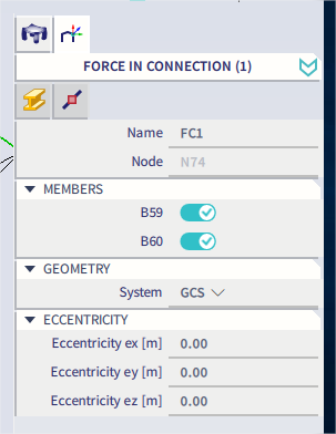
Connection forces - input
Workflow is definition of connection input node and then 2 possibilities are available:
1) switch off 1D member of interest in properties - in connection result table there will be displayed connection forces of this member missing in zero balance in the node
2) switch on only members of interest in properties - in connection result table per members there will be displayed connection forces of these 1D members
Properties
| Category | Property | Description / Notes | |||
|---|---|---|---|---|---|
| Name |
|
Name of connection | |||
| Node | Node where connection input is defined | ||||
| Members |
"name of members" On / Off |
List of 1D members connected to this node. Continuous 1D members are not taken into account. |
|||
| Geometry | System
GCS/ LCS |
||||
| Eccentricity |
|
Definition of eccentricity of connection point |
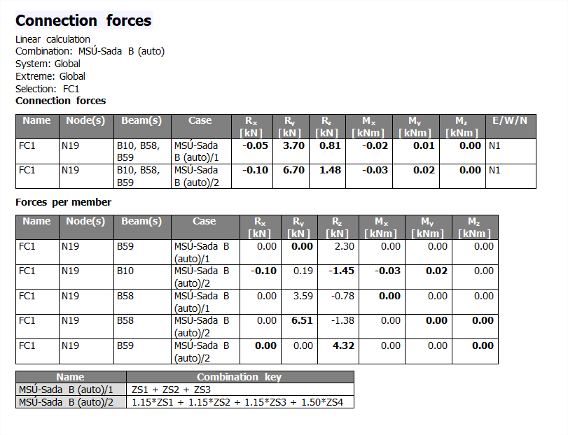
Connection forces - results
Properties
| Category | Property | Description / Notes | ||||
|---|---|---|---|---|---|---|
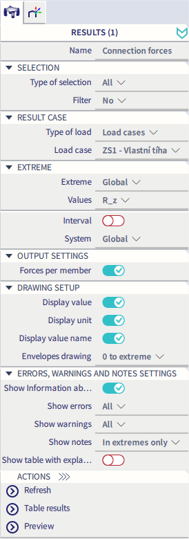
| Selections |
All / Current / Advanced / Named Selection
|
Specifies on what members the results are displayed
|
||||
| Filter
No / Material / WildCard / Layer |
Specifies the filter of members on what the results are displayed See "Filter" |
|||||
| Result case | Type of load
Load case / Combinations / Classes / Nonlinear Combinations |
Defines for what load the results are displayed. |
||||
| Extreme | Extreme
No / Node / Global |
Defines the position where extremes of result value are evaluated. note for "extreme no" option: If selected combination or class consist of too many linear combinations and thus it is not possible to display the results in full - conservative method that only displays results for linear combinations causing an extreme response of the structure is used instead. |
||||
| Values
R_x / R_y / R_z / M_x / M_y / M_z/ Components |
See table Valuesbelow. Components : possibility to choose more than one value and display them together in 3D window. Only selected values will be displayed in result tables. |
|||||
| Interval
On / Off |
Activation of interval of values for displaying in 3D window and in result tables. |
|||||
| Minimum [ ] | It is available only if Interval functionality is ON. User can define minimal value of interval. This item is unique for every type of unit used in Values. | |||||
| Maximum [ ] | It is available only if Interval functionality is ON. User can define maximal value of interval. This item is unique for every type of unit used in Values. | |||||
| System
LCS mesh element / Global |
Sets a coordination system which is used as referenced for displaying the results. |
|||||
| Output settings | Forces per member
On / Off |
Extra table with connection forces for all connected 1D members is displayed in preview | ||||
| Display info about used interval
On / Off |
It is possible to display or not display in header of result tables information about applied intervals. | |||||
| Drawing Setup |
|
|||||
| Errors, warnings and notes settings | "Errors, warnings and notes settings" |
Values
| Value | Description | Notes |
|---|---|---|
|
Rx |
connection reaction in direction of local axis x |
|
| Ry | connection reaction in direction of local axis y | |
| Rz | connection reaction in direction of local axis z | |
| Mx | connection moment around local axis x | |
| My | connection moment around local axis y | |
| Mz | connection moment around local axis z | |
| Components | possibility to choose more than one value and display them together in 3D window. Only selected values will be displayed in result tables. |