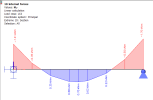
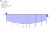
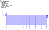
Not calculated internal forces
If required, the user can input to any 1D member and any load case his/her definition of the distribution of internal forces along the 1D member. The input of these "not-calculated" internal forces can be made in service Load. This user-input internal force is displayed as a normal load.
Type
It is possible to define up to 7 different components of internal forces or stresses: N, Vy, Vz, Mx, My, Mz, Sig Y, Sig Z.
Distribution
|
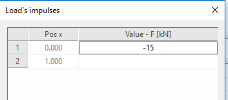
Uniform - 1 value is defined |
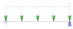
|
|
|
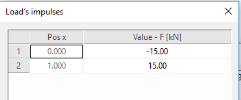
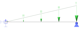
Trapez - 2 values on ends are defined |
||
|
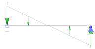
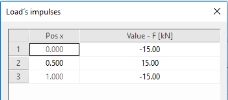
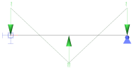
Triangle - 2 values on ends and 1 in the middle are defined |
||
|
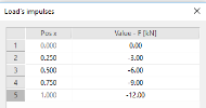
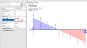
Polynomic - n values in n relative sections are input |
Polynomic distribution - details
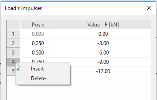
User can add n lines to polynomic distribution by right-click on the line. In the same way user can delete the row.
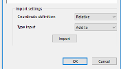
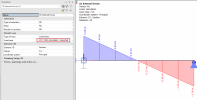
Other way how to import polynomic distribution is using import functionality.
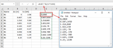
Import uses *.csv files which can be done manually in notepad. This syntax is required - based on the coordinate definition
Type of definition:
Add to - Adds values from csv file to current table - it is important to have same number of lines and same dx defined in both (table and csv)
Overwrite - Overwrites values in the table with definition from csv
Tip: *.csv file can be easily created from table results, when you export the table to excel, do adjustments (extract columns dx and force as a text) and copy the data to notepad, and save it as *.csv. This can be useful when you want to carry results from one structure to the same one, but don’t want to calculate everything in new model.
Note: Sig Y value can be applied in Member stress results for standard load cases. Sig Z can be taken in account only in prestress load cases.
Calculated results
Procedure to input not calculated internal forces
-
Open service Load.
-
Start function Not-calculated internal forces.
-
If required, type the name that serves better orientation in your project.
-
Select the type (one of the seven components mentioned above).
-
Select the distribution (one of the four stated above).
-
Press the three-dot button in item Parameters in order to open an extra dialogue and input the required values.
-
Confirm the parameters with [OK].
-
Confirm the load definition with [OK].
-
Position the load to required 1D members.

