Combined Shear Force, Axial Force and Bending Moment
The Combined Shear Force, Axial Force and Bending Moment Check is executed according to EN 1993-1-3 art. 6.1.10.
In the following paragraphs formula (6.27) is written out for both directions.
Shear Vy
In case of shear Vy formula (6.27) is written out as follows:
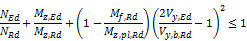
Remarks:
- Mf,Rd is taken as zero in case of Vy
(In case of weak axis bending, the ‘web’ becomes a ‘flange’. Since there is only a single ‘flange’ in that case, the moment resistance of this flange is negligible. In addition, in case of more webs like in a box section EN 1993-1-5 art. 7.1 (5) specifies Mf,Rd = 0. Therefore, as a general conservative approach for Vy the value of Mf,Rd is taken as 0.)
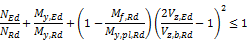
Shear Vz
In case of shear Vz formula (6.27) is written out as follows:
Remarks:
- According to [Ref.16] pp70 Mf,Rd is calculated as follows:
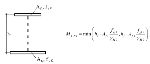
This is generalised in the following way:
- Only elements with element types I, UO and SO are accounted for
- Only elements which have an angle α with the principal y-y axis which is ≤ 45° are considered
In case there is only one or none of such element, Mf,Rd = 0. - Of these elements, the one with the lowest beff is considered. The width beff concerns the effective with of this element, read from the effective shape for bending.
- Af = beff * t with t the thickness of the considered element.
- Next only elements which have an angle α with the principal y-y axis which is > 45°are considered.
In case there are no such elements, set Mf,Rd = 0. - Of these elements, the one with the highest value of lc * sin(α) is considered, with lc the centreline length of the element.
- hf = lc * sin(α)
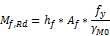
- Mf,Rd is now be calculated as:
- According to [Ref.16] pp70 Mpl,Rd is calculated as follows:
with Wpl read from the gross section properties.