Local Transverse Forces
The local transverse forces check is executed according to EN 1993-1-3 art 6.1.7 and following.
The check is executed on the positions where there is a jump in the Vz shear force diagram.
Remarks:
- The shear force diagram of both the actual member as well as adjacent members is evaluated. Adjacent members are defined as members which are in the same buckling system.
- The Flange Condition depends on the definition of the initial shape. In case there is an element with reinforcement type ROU or DEF the setting is taken as ‘Stiffened ’.
- The distances for One-flange/Two-flange and End/Interior are evaluated taking into account adjacent members. Adjacent members are defined as members which are in the same buckling system.
- In case the cross-section has multiple webs, for determining the load condition the maximal web height is used.
- As opposed to EN 1993-1-3 art. .1.7.2(4), the exact inputted bearing length ss will be used at all times i.e. the simplification of using the minimal length for both opposing loads is not supported.
- As indicated on EN 1993-1-3 Figure 6.6, the local transverse force resistance is taken relative to the support, not according to the principal z-axis. Therefore FEd, is determined according to the LCS axis system and not according to the principal axis system!
General Procedure
This paragraph specifies the general procedure to determine the local transverse web resistance which is applied for any type of cross-section except for FC 115 (Cold formed Omega).
In case the cross-section has any element with stiffener type RI, the procedure for stiffened webs is applied first.
In a first step the web height hw is determined for each ‘web’ element:
- Only elements of type I are accounted for.
In addition elements with stiffener types RUO and DEF are not accounted for. - For each of those elements i the centreline length lc,i is read from the Initial shape
- For each of those elements i the angle φi is determined as the angle of the element relative to the horizontal axis (based on Figure 6.6).
In addition, only elements with an angle φi ≥ 45° are accounted for. - The web height for each element i is calculated as:
![]()
- In case none of the cross-section elements fulfil the above conditions, the local transverse forces check is not supported for the cross-section.
When hw,i is determined, the local transverse resistance Rw,Rd,i for each of those elements is determined based on EN 1993-1-3 art. .1.7.2
The final cross-section resistance is taken as the sum of the individual element resistances.
By default, the local transverse resistance Rw,Rd,i is determined using EN 1993-1-3 Figure 6.7a & 6.7b.
The following table shows the relation between the loading conditions and the cases defined in the tables.
|
Loading Condition |
Table |
Case |
|---|---|---|
|
End One Flange (EOF) |
6.7a |
a) i) |
|
Interior One Flange (IOF) |
6.7a |
a) ii) |
|
End Two Flange (ETF) |
6.7b |
b) i) |
|
Interior Two Flange (ITF) |
6.7b |
b) ii) |
In case Web rotation prevented was set using Local Transverse Forces data instead of EN 1993-1-3 Figure 6.7a & 6.7b the formulas given in EN 1993-1-3 art. 6.1.7.2(4) are used.
The following table shows the relation between the loading conditions and the cases defined in this article.
|
Loading Condition |
Article |
Case |
|---|---|---|
|
End One Flange (EOF) |
art. 6.1.7.2(4) |
a) i) |
|
Interior One Flange (IOF) |
art. 6.1.7.2(4) |
a) ii) |
|
End Two Flange (ETF) |
art. 6.1.7.2(4) |
b) i) |
|
Interior Two Flange (ITF) |
art. 6.1.7.2(4) |
b) ii) |
Omega Sections
Specifically for FC 115 (Cold formed Omega) cross-sections the special procedure for sections with two or more unstiffened webs is applied. The local transverse resistance Rw,Rd,i for each of those webs is determined according to EN 1993-1-3 art. 6.1.7.3.
Other cross-sections with two or more unstiffened webs will always be calculated according to the General Procedure, not this special procedure.
The value of α in EN 1993-1-3 art. 6.1.7.3(5) is taken for ‘liner trays and hat sections’.
The following table shows the relation between the loading conditions and the categories defined in EN 1993-1-3 Figure 6.9.
|
Loading Condition |
Category |
|---|---|
|
End One Flange (EOF) |
1 |
|
Interior One Flange (IOF) |
1 |
|
End Two Flange (ETF) |
1 |
|
Interior Two Flange (ITF) |
2 |
Figure 6.9 does not directly specify ETF. However since two flange loading is specified as category 1 and End loading is also specified as category 1, the combined condition of ETF is considered as category 1.
According to [27] to use la = 10 mm for the end support reaction force (category 1) results in a very conservative resistance. A modification is given for case 2 and 3 of Figure 6.9: la = c + Ss.
By activating the setting “Use la correction in (6.18)” this modification is applied.
Stiffened Webs
This paragraph outlines the special procedure in case of stiffened webs according to EN 1993-1-3 art. 6.1.7.4.
This method is used only in case there are one or more elements with stiffener type RI
The procedure consists of four steps.
Step 1: Creating ‘composed’ webs
In a first step, ‘composed’ webs are created using the same procedure as outlined in "Sections with Internal stiffeners".
This includes the determination of the centreline length lc,i of those ‘composed’ webs.
Step 2: Evaluation of ‘composed’ webs
The special procedure outlined in EN 1993-1-3 art. 6.1.7.4 is only valid under certain conditions.
Therefore, each ‘composed’ web is evaluated to see if it meets the following requirements:
- There is one or more elements with stiffener type RI
- Each RI element should have element type I (i.e. it is at both sides connected to other elements signifying it’s a fold instead of a stiffener).
- Elements connected to this RI element should not have stiffener type RI. This implies that the procedure is not applied in case of neighbouring stiffener elements i.e. elements forming ‘one’ big stiffener.
Composed webs which do not meet these requirements are further evaluated in step 3.
Composed webs which meet all requirements are further evaluated in step 4.
Example:
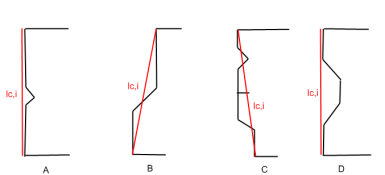
All four sections have ‘composed’ webs.
Section A contains two RI stiffeners which are connected. The web thus does not meet the requirements.
Section B contains a single RI stiffener which meets all the requirements. This stiffener is thus a ‘true’ two fold stiffener so the special article applies.
Section C contains several RI stiffeners however not all match the requirements (one is an outstand, others are connected etc). The web thus does not meet the requirements.
Section D has a composed web which contains two RI stiffeners. Both meet all the requirements and are thus ‘true’ two fold stiffeners. The special article applies.
Step 3: Composed webs which do NOT meet the requirements
For composed webs which do not meet the requirements, the special article is not valid. The local transverse force resistance of these webs will be determined according to the "General Procedure"
In this case, the centre line length lc,i of the composed web is used in the determination of hw.
The angle φi is determined as the angle of the centre line length relative to the horizontal axis.
Step 4: Composed webs which meet all requirements
For composed webs which meet all requirements, the special procedure outlined in EN 1993-1-3 art. 6.1.7.4 is applied.
The ‘system line’ of this web is taken as the centre line length lc,i.
The eccentricity e is determined at each end of an RI within the ‘composed’ web. Eccentricity emin and emax are then taken as the min and max value for the considered composed web.
In case the limit specified in formula (6.21) is not fulfilled, the special article is not applied and the composed web is considered as a web which does not meet all requirements. For such a web the procedure outlined in step 3 is applied.
For the developed width of the loaded flange bd any RI stiffeners of element Type I are always included, independent of their angle. RI stiffeners of element Type UO or SO are always ignored.
Connected flange elements which have a relative angle > 135° are accounted for as „one‟ flange for the determination of bd.
In case there is no connected flange, for example when using a general section, then bd is considered as zero. Practically this implies that there is no limit for κa,s.
The data is then used to determine κa,s according to formula (6.22).
The Rw,Rd,i value of the composed web is then calculated as:
Rw,Rd,i = κa,s * Rw,Rd,i,general
With Rw,Rd,i,general calculated according to the "General Procedure"
The value of hw,i for this composed web is calculated using the centre line lc,i of the composed web as outlined in step 3.