Validation of modal analysis: sum of masses
Dynamic analysis troubleshooting > modal analysis > protocol > sum of masses
After a modal analysis, first check the sum of masses given in the calculation protocol of eigen frequencies.
At the very least, estimate manually the total mass of the structure and check that the sum of masses provided in the protocol matches that estimate. Some more precise checks can be performed.
Most of the time, masses are generated from loads (mass groups linked to load cases). It is therefore simple, to obtain the total mass of the structure from the calculation protocol of linear analysis, by summing the total load of the load cases corresponding to the mass groups included in the considered mass combination, with the appropriate factors when relevant. When doing so, some specifics must be taken into account (see below).
Self-mass and self-weight of the structure
SCIA Engineer always takes into account the self-mass of the structure in the dynamic analysis. The self-mass and self-weight can be compared by looking at the values from the respective calculation protocols.
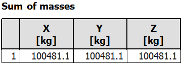
To obtain the mass of the structure alone, without any added external masses, create one empty mas group and one mass combination containing that mass group. The sum of masses in the protocol will correspond of the self-mass of the structure. The self-weight of the structure is obtained from the calculation protocol of linear calculation.
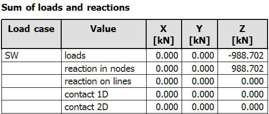
In theory, the self-weight should be exactly equal to the self-mass multiplied by the acceleration of gravity, g.

However, two factors can affect that relationship:
- nodal masses (understand here masses attached to each node of the finite element mesh) that are directly attached to a rigid support are ignored in the dynamic calculation; they cannot move and are therefore irrelevant for the dynamic analysis
- property modifiers may be used in SCIA Engineer to alter the value of the self-weight and self-mass separately, thus breaking the direct correspondence between the two values
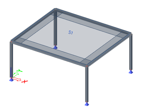
In this example, it is the first factor that affects the mass. The mass of each finite element is distributed to the nodes of the mesh. In this simple platform, where no mesh refinement is used, the mass of each column is distributed to its end nodes, i.e. 50% at the top and 50% at the bottom. As the bottom node is directly connected to a rigid, pinned support, the mass of the lower half of the columns is ignored in the dynamic analysis.
The weight of the lower half of the columns can be calculated:

which corresponds to the observed difference of weight:

That difference is, of course, affected by the mesh settings. Refining the mesh of the columns would reduce that difference, as the mass would then be distributed to more intermediate mesh nodes.
That type of discrepancy is no limited to self-weight and self-mass. Any distributed mass - defined manually or generated from a distributed load - applied to a member that is directly connected to a rigid support would be affected in the same way, as well as a concentrated mass assigned to a supported node.
Masses generated from loads
A mass group may be linked to a load case and masses generated from the gravity loads of that load case. In such a case, the check is quite straight forward. as long as no distributed loads are applied to members that are directly attached to rigid supports, the direct relationship between the loads and the generated masses will be fulfilled.
However, as mentioned above, the self-mass of the structure is always automatically included in a mass combination. To compare the cumulated mass for another mass group, it will be necessary to know the value of the self-mass. For that, the simplest way is to proceed as described above, by creating a separate mass combination containing only an empty mass group.
In our simple example, the mass combination contains one mass group with a uniform surface mass, generated from a 5 kN/m2 surface load. The total mass for that combination and the total load for the described load case are
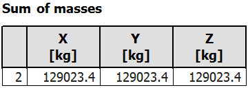
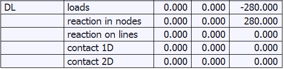
The mass of the second mass group can be deducted from the previous calculation for the self-mass and self-weight

and the corresponding weight is

which corresponds to the sum of loads of load case DL.
Manually defined masses
In case masses are defined manually, the only remaining solution is to calculate manually the total mass for comparison with the obtained value.The same rules as before apply for members directly connected to rigid supports.
Non-isotropic masses
In most cases, the mass components in all directions (X, Y, Z) are identical. There are a few cases, however, where the mass components in directions X, Y and Z can differ:
Non-isotropic boundary conditions
In case a mass is attached directly to a support with rigid boundary conditions, that mass is not considered in the dynamic analysis (topic mentioned above in the Self-mass and self-weight of the structure section). As long as all components X, Y and Z are identically supported, the total mass components remain identical. When boundary conditions are different in some direction, the mass components might also differ, when some mass is assigned directly to such a node.
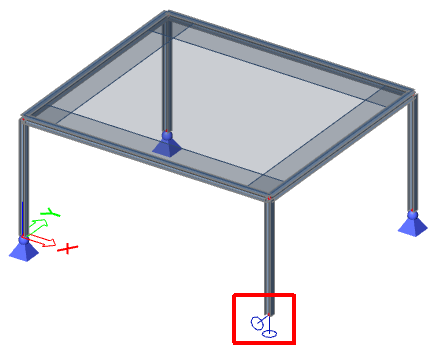
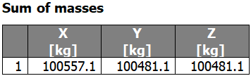
In the example above, the displacement in X-direction is free on one of the supports. As a consequence, the mass from the lower half of the corresponding column is considered in the analysis, unlike for the other 3 columns, and the total mass in the X-direction is slightly higher than in the other two directions.
The mass difference is

which corresponds to the mass of the lower half of the column

Mass components filtering
The advanced settings of the solver setup allow to disable some mass components for dynamic analysis. This is convenient, for instance, to remove all vertical modes from the calculation, in case they are not desired.
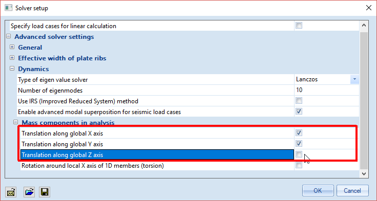
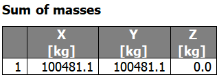
In this example, the sum of masses in the Z-direction is zero, due to the selected settings in the solver setup. As a consequence, no eigenmode is computed in the Z-direction.
Directional mass coefficients
In some special cases, it is interesting to apply correction coefficients to some components of individual masses. This can be done when masses are defined manually. In the properties of masses, correction coefficients may be applied separately in each global direction.
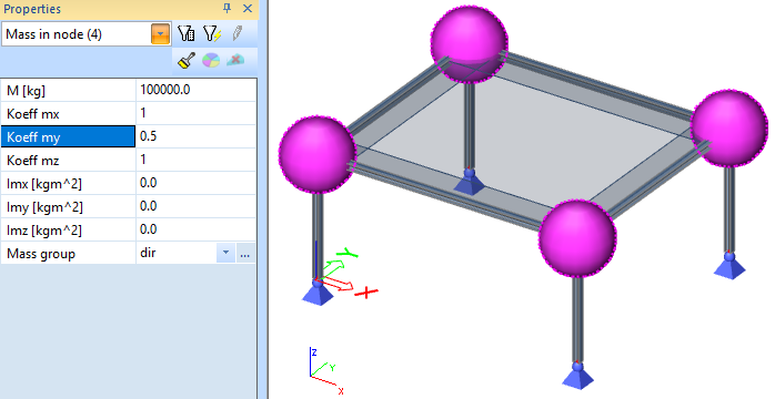
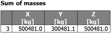
In this example, 4 100t nodal masses have been added to the model. A coefficient 0.5 has been applied in the Y-direction. As a consequence, the sum of masses in that direction is reduced. The mass difference is

The difference due to the direction coefficient is

Next step: check frequencies