Response spectrum generator according to DIN (German standard)
Procedure to input a new DIN seismic spectrum
- Expand branch Libraries of the main tree menu.
- Expand sub-branch Loads.
- Start function Seismic spectrum to open the Seismic Spectrum Manager.
- Click button .
- In combo box Input type select option DIN - German standard.
- Review and, if required, adjust the spectrum parameters.
- Click button to review or modify the code-defined parameters of the spectrum.
- Confirm the code parameters with .
- Click to confirm the spectrum.
- Close the Seismic Spectrum Manager.
Spectrum definition and code parameters
A response spectrum can be defined according to DIN by selecting DIN - German standard as Input type.
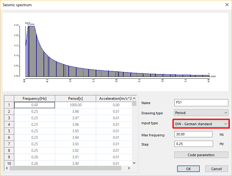
Max frequency & Step
The values of the spectrum are generated between a maximum period of 4 seconds (=0.25 Hz) and the input maximum frequency, using the input Step value.
Code parameters
This button opens the dialogue defining the code-dependent parameters.
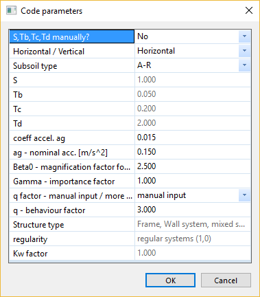
S, Tb, Tc, Td manually?
When this option is No, S, Tb, Tc, Td are obtained a table, depending on the selected subsoil type
When this option is Yes, S, Tb, Tc, Td are defined manually
Horizontal / Vertical
Direction of the seismic action: horizontal or vertical
Subsoil type
Category of subsoil (A-R, B-R, C-R, B-T, C-T, C-S)
S
Subsoil factor, obtained from table or defined manually
Tb
Lower limit of the period of the constant spectral acceleration branch, obtained from table or defined manually
Tc
Upper limit of the period of the constant spectral acceleration branch, obtained from table or defined manually
Td
Value defining the beginning of the constant displacement response range of the spectrum, obtained from table or defined manually
coeff. accel. ag
Value of the nominal acceleration expressed as a multiple of the acceleration of gravity g
ag - nominal acc.
Nominal ground acceleration
Beta0
Magnification factor for the acceleration spectra
Gamma
Importance factor
q factor - manual input / more parameters
When this option is set as manual input, the value of q is defined manually
When this option is set as more parameters, the value of q is calculated
q
Behaviour factor
Structure type
Type of shear-resisting system
- Frame, wall system, mixed system (3.0)
- Core system (2.0)
- Reverse pendulum system (1.7)
Regularity
Regularity of the shear resisting system
- regular systems (1.0)
- non-regular systems (0.8)
Kw factor
Correction factor for the calculation of q
Theoretical background
Design response spectrum
The seismic response spectrum is defined as

The tabulated values of S, Tb, Tc, Td for the horizontal spectrum are defined as
| Subsoil type | S [-] | TB [s] | TC [s] | TD [s] |
| A-R | 1.00 | 0.05 | 0.20 | 2.0 |
| B-R | 1.25 | 0.05 | 0.25 | 2.0 |
| C-R | 1.50 | 0.05 | 0.30 | 2.0 |
| B-T | 1.00 | 0.10 | 0.30 | 2.0 |
| C-T | 1.25 | 0.10 | 0.40 | 2.0 |
| C-S | 0.75 | 0.10 | 0.50 | 2.0 |
For vertical spectrum, use the values defined above, modified as follows:
TC = 0.20 s
Behaviour factor
When requested, the behaviour factor is calculated as

| Structure type | q0 |
| Frame, wall system, mixed system | 3.0 |
| Core system | 2.0 |
| Reverse pendulum system | 1.7 |
| Regularity | Kr |
| Regular systems | 1.0 |
| Non-regular systems | 0.8 |
Kw is defined by the user.