Response spectrum generator according to EN1998-1:2004 (Eurocode)
Procedure to input a new EN1998 seismic spectrum
- Expand branch Libraries of the main tree menu.
- Expand sub-branch Loads.
- Start function Seismic spectrum to open the Seismic Spectrum Manager.
- Click button .
- In combo box Input type select option Eurocode.
- Review and, if required, adjust the spectrum parameters.
- Click button to review or modify the code-defined parameters of the spectrum.
- Confirm the code parameters with .
- Click to confirm the spectrum.
- Close the Seismic Spectrum Manager.
Spectrum definition and code parameters
A response spectrum can be defined according to EN1998-1:2004 by selecting Eurocode as Input type.
This generator supports only the standard Eurocode 8 seismic spectrum. National Annexes are not supported.
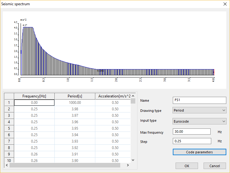
Max frequency & Step
The values of the spectrum are generated between a maximum period of 4 seconds (=0.25 Hz) and the input maximum frequency, using the input Step value.
Code parameters
This button opens the dialogue defining the code-dependent parameters.
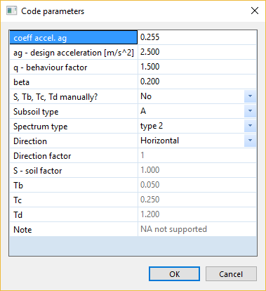
coeff. accel. ag
Value of the design acceleration expressed as a multiple of the acceleration of gravity g
ag - design acceleration
Design ground acceleration on type A ground
q - behaviour factor
Behaviour factor
beta
Lower bound factor for the horizontal design spectrum
S, Tb, Tc, Td manually?
When this setting is No, the values S, Tb, Tc, Td are obtained from table 3.2, 3.3 or 3.4, depending on the subsoil type, spectrum type and direction of the seismic action
When this setting is Yes, the values S, Tb, Tc, Td are input manually
Subsoil type
Ground type (A, B, C, D, E), as described in table 3.1
Spectrum type
Type 1 or 2, as described in 3.2.2.2(2)P
Direction
Direction of the seismic action, horizontal or vertical
Direction factor
Correction factor that depends on the selection direction and spectrum type, as defined in table 3.4
S - soil factor
Soil factor, obtained from table 3.2 or 3.3, depending on the subsoil type and spectrum type
Tb
Lower limit of the period of the constant spectral acceleration branch, obtained from table 3.2, 3.3 or 3.4, depending on the subsoil type, spectrum type and direction of the seismic action
Tc
Upper limit of the period of the constant spectral acceleration branch, obtained from table 3.2, 3.3 or 3.4, depending on the subsoil type, spectrum type and direction of the seismic action
Td
Value defining the beginning of the constant displacement response range of the spectrum, obtained from table 3.2, 3.3 or 3.4, depending on the subsoil type, spectrum type and direction of the seismic action
For all code-defined values, the recommended values defined in the EN1998-1:2004 are used
Theoretical background
Design spectrum for the horizontal component of the seismic action
According to EN1998-1:2004 eq. (3.13) through (3.16):

where
ag is the design ground acceleration for a type A ground, defined as

γI is the importance factor, depending on the type of structure
agR is the reference peak ground acceleration on type A ground, defined in the relevant National Annex
q is the behaviour factor
β is the lower bound factor for the horizontal design spectrum; the recommended value is 0.2
S, TB, TC, TD are the soil parameters, defined in tables 3.2 and 3.3
EN1998-1:2004 Table 3.2: Values of the parameters describing the recommended Type 1 elastic response spectra
| Ground type | S [-] | TB [s] | TC [s] | TD [s] |
| A | 1.0 | 0.15 | 0.4 | 2.0 |
| B | 1.2 | 0.15 | 0.5 | 2.0 |
| C | 1.15 | 0.20 | 0.6 | 2.0 |
| D | 1.35 | 0.20 | 0.8 | 2.0 |
| E | 1.4 | 0.15 | 0.5 | 2.0 |
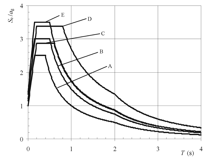
EN1998-1:2004 Figure 3.2: Recommended Type 1 elastic response spectra for ground types A to E (5% damping)
EN1998-1:2004 Table 3.3: Values of the parameters describing the recommended Type 2 elastic response spectra
| Ground type | S [-] | TB [s] | TC [s] | TD [s] |
| A | 1.0 | 0.05 | 0.25 | 1.2 |
| B | 1.35 | 0.05 | 0.25 | 1.2 |
| C | 1.5 | 0.10 | 0.25 | 1.2 |
| D | 1.8 | 0.10 | 0.30 | 1.2 |
| E | 1.6 | 0.05 | 0.25 | 1.2 |
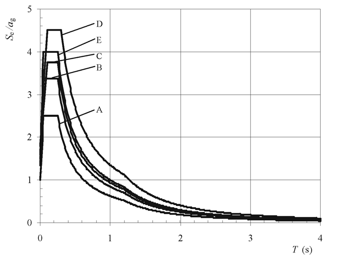
EN1998-1:2004 Figure 3.3: Recommended Type 2 elastic response spectra for ground types A to E (5% damping)
Desgin spectrum for the vertical component of the seismic action
For the vertical component, the same formulation as for the horizontal component is used, with the following assumptions:
ag is replaced by avgas defined in table 3.4
S = 1.0
q is not greater than 1.5
TB, TC, TD are obtained from table 3.4
EN1998-1:2004 Table 3.4: Recommended values of parameters describing the vertical elastic response spectra
|
Spectrum |
avg/ag [-] | TB [s] | TC [s] | TD [s] |
| Type 1 | 0.90 | 0.05 | 0.15 | 1.0 |
| Type 2 | 0.45 | 0.05 | 0.15 | 1.0 |
Elastic spectrum
Only the formulation of the seismic design spectrum is available in the EN1998 spectrum generator of SCIA Engineer.
The elastic spectrum may be approximated using the following settings:


Doing so will, however, underestimate the value of the spectral acceleration for short periods (T < TB). If a more accurate definition of the elastic spectrum is needed, manual input of the spectrum should be used.