Response spectrum generator according to ASCE/SEI 7-10 (IBC)
Procedure to input a new IBC seismic spectrum
- Expand branch Libraries of the main tree menu.
- Expand sub-branch Loads.
- Start function Seismic spectrum to open the Seismic Spectrum Manager.
- Click button .
- In combo box Input type select option IBC.
- Review and, if required, adjust the spectrum parameters.
- Click button to review or modify the code-defined parameters of the spectrum.
- Confirm the code parameters with .
- Click to confirm the spectrum.
- Close the Seismic Spectrum Manager.
Spectrum definition and code parameters
A response spectrum can be defined according to ASCE/SEI 7-10 by selecting IBC as Input type .
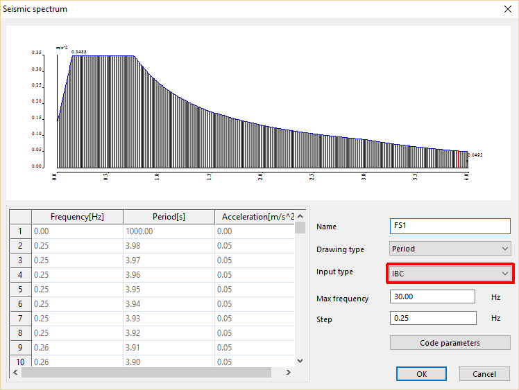
Max frequency & Step
The values of the spectrum are generated between a maximum period of 4 seconds (=0.25 Hz) and the input maximum frequency, using the input Step value.
Code parameters
This button opens the dialogue defining the code-dependent parameters.
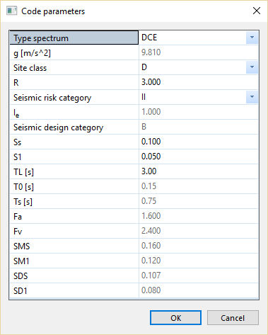
Type spectrum
- DCE: Design Considered Earthquake (default)
- MCE: Maximum Considered Earthquake (= 1.5 * DCE)
g
Input. Acceleration of gravity, defined in the project settings
Site class
Input. Site class according to Section 11.4.2 and Chapter 20
R
Input. Response modification coefficient according to Table 12.2-1 Design coefficients and Factors for seismic force-resisting systems
Seismic risk category
Input. Risk category according to Table 1.5-1 Risk category of buildings and other structures for flood, wind, snow, earthquake and ice loads
Ie
Calculated. Importance factor according to Table 1.5-2
Seismic design category
Calculated. Seismic design category according to Section 11.6
Ss
Input. Mapped MCER, 5 percent damped, spectral response acceleration parameter at short periods as defined in Section 11.4.1
S1
Input. Mapped MCER, 5 percent damped, spectral response acceleration parameter at period 1s as defined in Section 11.4.1
TL
Input. Long-period transition period as defined in Section 11.4.5
T0
Calculated. 0.2 * SD1 / SDS
Ts
Calculated. SD1 / SDS
Fa
Calculated. Short-period site coefficient (at 0.2s period) according to Section 11.4.3
Fv
Calculated. Long-period site coefficient (at 1.0s period) according to Section 11.4.3
SMS
Calculated. MCER, 5 percent damped, spectral response acceleration parameter at short periods adjusted for site class effects as defined in Section 11.4.3
SM1
Calculated. MCER, 5 percent damped, spectral response acceleration parameter at a period of 1s adjusted for site class effects as defined in Section 11.4.3
SDS
Calculated. Design, 5 percent damped, spectral response acceleration parameter at short periods as defined in Section 11.4.4
SD1
Calculated. Design, 5 percent damped, spectral response acceleration parameter at a period of 1s as defined in Section 11.4.4
Theoretical background
Fa is obtained from Table 11.4-1. Use linear interpolation for intermediate values of Ss.
| Site Class | Ss≤0.25 | Ss=0.5 | Ss=0.75 | Ss=1.0 | Ss≥1.25 |
| A | 0.8 | 0.8 | 0.8 | 0.8 | 0.8 |
| B | 1.0 | 1.0 | 1.0 | 1.0 | 1.0 |
| C | 1.2 | 1.2 | 1.1 | 1.0 | 1.0 |
| D |
1.6 |
1.4 | 1.2 | 1.1 | 1.0 |
| E | 2.5 | 1.7 | 1.2 | 0.9 | 0.9 |
| F | see Section 11.4.7; the corresponding values of Fa must be defined by the user | ||||
Fv is obtained from Table 11.4-2. Use linear interpolation for intermediate values of S1.
| Site Class | S1≤0.1 | S1=0.2 | S1=0.3 | S1=0.4 | S1≥0.5 |
| A | 0.8 | 0.8 | 0.8 | 0.8 | 0.8 |
| B | 1.0 | 1.0 | 1.0 | 1.0 | 1.0 |
| C | 1.7 | 1.6 | 1.5 | 1.4 | 1.3 |
| D | 2.4 | 2.0 | 1.8 | 1.6 | 1.5 |
| E | 3.5 | 3.2 | 2.8 | 2.4 | 2.4 |
| F | see Section 11.4.7; the corresponding values of Fv must be defined by the user | ||||


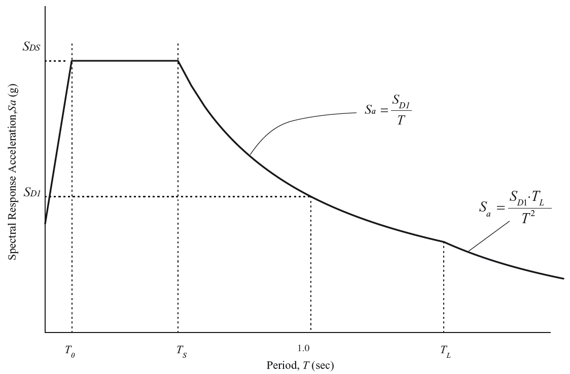

Final acceleration value:

Notes about ELF calculation
In Equivalent Lateral Forces calculation, some additional criteria are applied. Those criteria are not implemented in the definition of the IBC spectrum generator. They are applied only in the calculation of horizontal forces in the ELF procedure.
Minimum value of Cs
The parameter Cs shall not be taken less than the following:

The Cs,min criterion is applied separately to each component (X, Y) of ELF load cases
Maximum value of T
The fundamental period T shall not be taken greater than

where Ta is the approximate fundamental period as defined in Section 12.8.2.1
Cu is taken from Table 12.8-1 (Coefficient for upper limit on calculated period):
| SD1 | Cu |
| ≥ 0.4 | 1.4 |
| 0.3 | 1.4 |
| 0.2 | 1.5 |
| 0.15 | 1.6 |
| ≤0.1 | 1.7 |
Approximate fundamental period according to ASCE 7-10 12.8.2.1
The fundamental period of buildings may be approximated are follows:

where
Ta = approximate fundamental period
hn = height of the top mass of the building from the reference level, in [m]
Ct and x are taken from Table 12.8-2:
| Structure type | Ct | x |
| Moment-resisting frame systems in which the frames resist 100% of the required seismic force
and are not enclosed or adjoined by components that are more rigid and will prevent the frames from deflecting where subjected to seismic forces: |
||
| - Steel moment-resisting frames | 0.0724 | 0.8 |
| - Concrete moment-resisting frames | 0.0466 | 0.9 |
| Steel eccentrically braced frames in accordance with Table 12.2-1 lines B1 or D1 | 0.0731 | 0.75 |
| Steel buckling-restrained braced frames | 0.0731 | 0.75 |
| All other structural systems | 0.0488 | 0.75 |
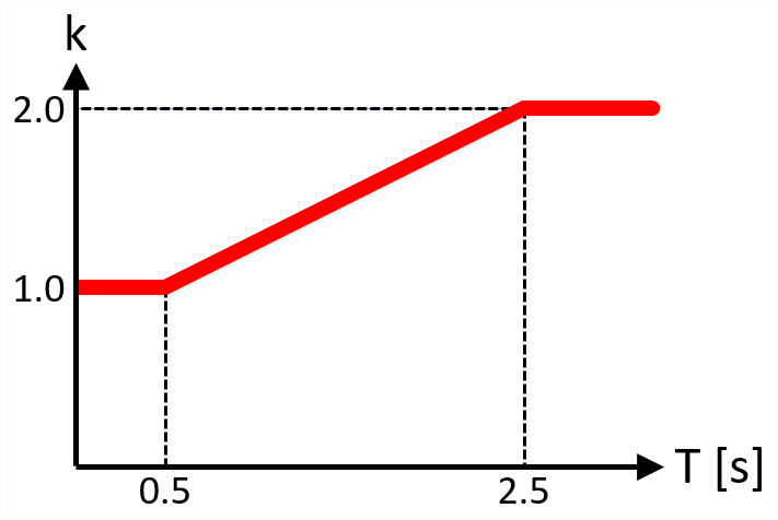
Vertical distribution of accelerations according to ASCE 7-10 12.8.3
The total horizontal seismic force (base shear) is distributed to the storeys according to a distribution assumption. Additionally to the standard options (linear, modal shape), the ASCE 7-10 defines a polynomial distribution as follows:

and

and

where
Fi = seismic force applied at level i
Ftot = total seismic force (base shear)
Cvi = vertical distribution coefficient
Mi = mass at level i
hi = height of level i (Z-coordinate measured from reference level)
k = exponent
T = fundamental period