Response spectrum generator according to NPR 9998:2015 (Netherlands standard)
Procedure to input a new NPR 9998 seismic spectrum
- Expand branch Libraries of the main tree menu.
- Expand sub-branch Loads.
- Start function Seismic spectrum to open the Seismic Spectrum Manager.
- Click button .
- In combo box Input type select option NPR 9998 - Netherlands standard.
- Review and, if required, adjust the spectrum parameters.
- Click button to review or modify the code-defined parameters of the spectrum.
- Confirm the code parameters with .
- Click to confirm the spectrum.
- Close the Seismic Spectrum Manager.
Spectrum definition and code parameters
A response spectrum can be defined according to NPR 9998:2015 clause 3.2.2.2 by selecting NPR 9998 - Netherlands standard as Input type.
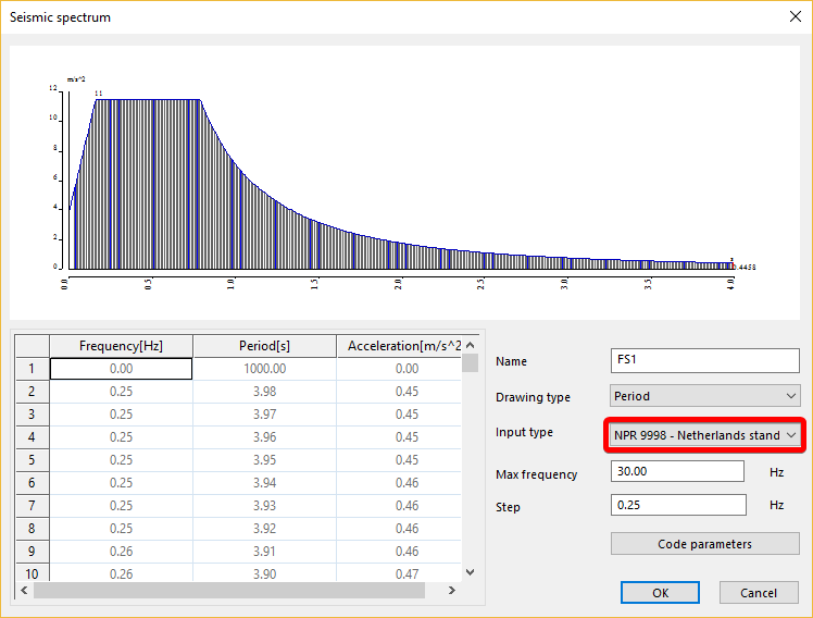
Max frequency & Step
The values of the spectrum are generated between a maximum period of 4 seconds (=0.25 Hz) and the input maximum frequency, using the input Step value.
Code parameters
This button opens the dialogue defining the code-dependent parameters.
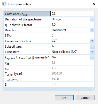
Coeff. accel. ag,ref
Reference value of the peak ground acceleration from seismic map, expressed as a multiple of g
Definition of the spectrum
Type of spectrum definition, elastic or design
q - behaviour factor
Behaviour factor (only for design spectrum)
Direction
Direction of the seismic action, horizontal or vertical
ξ [%]
Relative damping
Consequence class
CC1 - CC3 for elastic spectrum
CC1A, CC1B, CC2, CC3 for design spectrum
Subsoil type
Types of soil: A, B, C
Limit state
Near collapse (NC), Significant damage (SD), Damage limitation(DL)
kag, γm, TLS,ref, Tref, β manually?
No: kag, γm, TLS,ref, Tref, β are defined according to the selected consequence class and subsoil type
Yes: kag, γm, TLS,ref, Tref, β are defined by the user
kag
Coefficient depending on the consequence class and the subsoil type
γm
Defined from spectrum definition type, consequence class, subsoil type, and limit state or user defined
TLS,ref
Reference return time of the reference seismic load, depending on the considered limit state
Tref
Reference period
β
Reliability index
γm, TLS,ref, Tref and β are displayed only for information. They are not used in the calculation of the spectrum.
Theoretical background
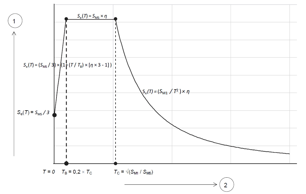
Horizontal elastic spectrum acc. NPR 9998:2015 3.2.2.2.1


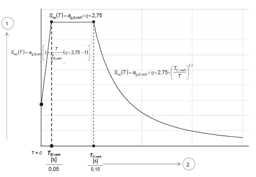
Vertical elastic spectrum acc. NPR 9998:2015 3.2.2.2.2


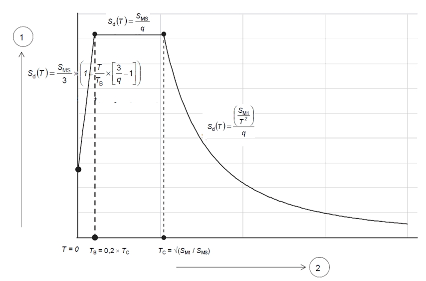
Horizontal design spectrum acc. NPR 9998:2015 3.2.2.2.3

TB, TC, SMS, SM1 are the same as for the horizontal elastic spectrum.
Vertical design spectrum acc. NPR 9998:2015 3.2.2.2.3

TB,vert, TC,vert, ag,d,vert are the same as for the vertical elastic spectrum.
Tabulated values from NPR 9998:2015 tables 2.1 and 2.2
| Definition of the spectrum | Consequence class | Subsoil type | Limit state | kag | γm | TLS,ref [yr] | Tref [yr] | β |
| Elastic | CC3 | A | NC | 1.9 | 1.3 | 3600 | 50 | 3.1 |
| Elastic | CC3 | A | SD | 1.7 | 1 | 2500 | 50 | 3.1 |
| Elastic | CC3 | A | DL | 1 | 1 | 500 | 50 | 3.1 |
| Elastic | CC3 | B | NC | 1.9 | 1.3 | 3600 | 50 | 3.1 |
| Elastic | CC3 | B | SD | 1.5 | 1 | 1500 | 50 | 3.1 |
| Elastic | CC3 | B | DL | 0.7 | 1 | 200 | 50 | 3.1 |
| Elastic | CC2 | A | NC | 1.6 | 1.2 | 1800 | 50 | 2.7 |
| Elastic | CC2 | A | SD | 1.5 | 1 | 1500 | 50 | 2.7 |
| Elastic | CC2 | A | DL | 0.7 | 1 | 200 | 50 | 2.7 |
| Elastic | CC2 | B | NC | 1.6 | 1.2 | 1800 | 50 | 2.7 |
| Elastic | CC2 | B | SD | 1.3 | 1.3 | 1000 | 50 | 2.7 |
| Elastic | CC2 | B | DL | 0.5 | 1 | 100 | 50 | 2.7 |
| Elastic | CC2 | C | NC | 1.6 | 1.2 | 1800 | 50 | 2.7 |
| Elastic | CC2 | C | SD | 1 | 1 | 500 | 50 | 2.7 |
| Elastic | CC2 | C | DL | 0.4 | 1 | 50 | 50 | 2.7 |
| Elastic | CC1 | A | NC | 1.4 | 1.1 | 1200 | 50 | 2.4 |
| Elastic | CC1 | A | SD | 1 | 1 | 500 | 50 | 2.4 |
| Elastic | CC1 | A | DL | 0.4 | 1 | 50 | 50 | 2.4 |
| Elastic | CC1 | B | NC | 1.4 | 1.1 | 1200 | 50 | 2.4 |
| Elastic | CC1 | B | SD | 0.7 | 1 | 200 | 50 | 2.4 |
| Elastic | CC1 | B | DL | 0.3 | 1 | 30 | 50 | 2.4 |
| Elastic | CC1 | C | NC | 1.4 | 1.1 | 350 | 15 | 3 |
| Elastic | CC1 | C | SD | 1.4 | 1.1 | 350 | 15 | 3 |
| Elastic | CC1 | C | DL | 1.4 | 1.1 | 350 | 15 | 3 |
| Design | CC3 | A | NC | 1.8 | 1.3 | 3000 | 15 | 3.3 |
| Design | CC3 | A | SD | 1.8 | 1.3 | 3000 | 15 | 3.3 |
| Design | CC3 | A | DL | 1.8 | 1.3 | 3000 | 15 | 3.3 |
| Design | CC3 | B | NC | 1.8 | 1.3 | 3000 | 15 | 3.3 |
| Design | CC3 | B | SD | 1.8 | 1.3 | 3000 | 15 | 3.3 |
| Design | CC3 | B | DL | 1.8 | 1.3 | 3000 | 15 | 3.3 |
| Design | CC2 | A | NC | 1.5 | 1.2 | 1500 | 15 | 3.1 |
| Design | CC2 | A | SD | 1.5 | 1.2 | 1500 | 15 | 3.1 |
| Design | CC2 | A | DL | 1.5 | 1.2 | 1500 | 15 | 3.1 |
| Design | CC2 | B | NC | 1.5 | 1.2 | 1500 | 15 | 3.1 |
| Design | CC2 | B | SD | 1.5 | 1.2 | 1500 | 15 | 3.1 |
| Design | CC2 | B | DL | 1.5 | 1.2 | 1500 | 15 | 3.1 |
| Design | CC2 | C | NC | 1.5 | 1.2 | 1500 | 15 | 3.1 |
| Design | CC2 | C | SD | 1.5 | 1.2 | 1500 | 15 | 3.1 |
| Design | CC2 | C | DL | 1.5 | 1.2 | 1500 | 15 | 3.1 |
| Design | CC1B | A | NC | 1.2 | 1.1 | 800 | 15 | 2.8 |
| Design | CC1B | A | SD | 1.2 | 1.1 | 800 | 15 | 2.8 |
| Design | CC1B | A | DL | 1.2 | 1.1 | 800 | 15 | 2.8 |
| Design | CC1B | B | NC | 1.2 | 1.1 | 800 | 15 | 2.8 |
| Design | CC1B | B | SD | 1.2 | 1.1 | 800 | 15 | 2.8 |
| Design | CC1B | B | DL | 1.2 | 1.1 | 800 | 15 | 2.8 |
| Design | CC1A | A | NC | 1.2 | 1.1 | 200 | 1 | 2.8 |
| Design | CC1A | A | SD | 1.2 | 1.1 | 200 | 1 | 2.8 |
| Design | CC1A | A | DL | 1.2 | 1.1 | 200 | 1 | 2.8 |