Karman Vibration
Karman vibration handles on the transverse vibration of cylindrical structures due to wind.
First the theory is explained in which reference is made to the Harmonic load since Vortex shedding is a special case of harmonic loading.
Background
One of the most important mechanisms for wind-induced oscillations is the formation of vortices (concentrations of rotating fluid particles) in the wake flow behind certain types of structures such as chimneys, towers, suspended pipelines…
At a certain (critical) wind velocity, the flow lines do not follow the contours of the body, but break away at some points, and then the vortices are formed.
These vortices are shed alternately from opposite sides of the structure and give rise to a fluctuating load perpendicular to the wind direction. The following figure illustrates the vortex shedding for flow past a circular cylinder. The created pattern is often referred to as the Karman vortex trail:
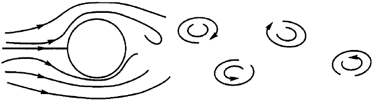
When a vortex is formed on one side of the structure, the wind velocity increases on the other side. This results in a pressure difference on the opposite sides and the structure is subjected to a lateral force away from the side where the vortex is formed. As the vortices are shed at the critical wind velocity alternately first from one side then the other, a harmonically varying lateral load with the same frequency as the frequency of the vortex shedding is formed.
The frequency of the vortex shedding is given by:

|
(4.1) |
With:
S = Non-dimensional constant referred to as the Strouhal Number; For a cylinder this is taken as 0,2.
d = Width of the body loaded by the wind [m]; For a cylinder this equals the outer-diameter.
v = The mean velocity of the wind flow [m/s]
The manner in which vortices are formed is a function of the Reynolds number Re, which is given by:

|
(4.2) |
The Reynolds number characterizes three major regions:
| Subcritical |

|
| Supercritical |

|
| Transcritical |

|
In general large Reynolds numbers stays for turbulent flow.
For chimneys with circular cross section the flow is either in the supercritical or transcritical range for wind velocities of practical interest.
If the vortex shedding frequency coincides with the natural frequency of the structure (resonance) quite large across-wind amplitudes of vibration will result unless sufficient damping is present.
In this case, formula (4.1) can be rewritten to calculate the critical wind velocity at which resonance occurs:

|
(4.3) |
With:
f = Natural frequency of the structure
The across-wind forces per unit length caused by the vortex shedding can be approximated by the following formula:

|
(4.4) |
With:
 = air density taken as 1,25 kg/m³
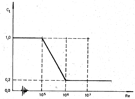
 = alift coefficient that fluctuates in a harmonic or random manner and depends of the Reynolds number. The following figure shows
this relation when Ct is proportional to the mode shape.
If the vortex shedding is taken as harmonic, equation (4.4) can be written as:

|
(4.5) |
According to reference, assuming a constant wind profile, the equivalent modal force due to the fluctuating lift force of equation (4.5) is given by:

|
(4.6) |
With:
 = Modal shape at height z
H = Total height of the structure
The dynamic amplitude Y at resonance can be written as:

|
(4.7) |
The static deformation YS is given by:

|
(4.8) |
M is the equivalent modal mass of a prismatic member given by:

|
(4.9) |
With:
 = The mass per unit height
When combining formulas (4.7) and (4.8) the maximum response of a SDOF system subjected to a harmonic excitation may be written as:

|
(4.10) |
It follows that when the vortex shedding occurs with the same frequency as the natural frequency of the structure, the maximal amplitude is given by:

|
(4.11) |
When it is assumed that the mass per unit height is constant and that the lift coefficient is proportional to the mode shape, formula (4.11) can be simplified to the following:

|
(4.12) |
This equation may be used as a first estimate of likely response of the structure.
Practical use
Karman Vibration in SCIA Engineer
In SCIA Engineer, the Vortex Shedding was implemented according the Czech loading standard.
The effect is only taken into account if the critical wind velocity calculated by formula (4.3) is between a minimal and maximal value. These two extremes can be defined by the user. The default values are taken as 5 m/s and 20 m/s.
In addition to formula (4.11), in SCIA Engineerit is possible to specify the length of the structure where the Von Karman effect can occur. For each geometric node of the structure, it is possible to relate a length of the cylinder to the node. This implies that, in order to obtain precise results, the structure should be modelled with sufficient geometric nodes.
By default the effect can occur over the entire height of the structure however, when there are specific obstacles on the surface of a chimney for example, these obstacles will hamper the formation of the vortices and thus reduce the Von Karman effect. In practice, this is exactly the solution to suppress vortex-induced vibration, the fitting of special ribs on the surface of the cylinder.
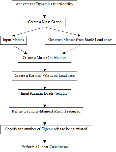
The following diagram shows the required steps to perform a Vortex Shedding calculation:
Equations used in SCIA Engineer:
Coefficients for the direction of the vortex shedding action

|
(4.13) |

where
 is the direction of the wind action defined in the load case parameters
Critical wind velocity (listed in the calculation protocol)

|
(4.14) |
where
 is the diameter of the structure defined in the load case parameters
 is the frequency of the selected mode shape
 is the index of the selected mode shape for Karman loading, defined in the load case parameters; it may also be determined automatically (default)
Reynolds number (listed in the calculation protocol)

|
(4.15) |
Drag coefficient (listed in the calculation protocol)
|
(4.16) |


Load per unit length at the point of maximum deflection of the selected mode shape (listed in the calculation protocol)

|
(4.17) |
where
 is the density of air
Maximum horizontal modal displacement for the selected mode I (listed in the calculation protocol)

|
(4.18) |
where
 is the value of modal displacement at node j in direction k for mode I
 is the number of nodes with applied Karman loads
Force at node j in direction k

|
(4.19) |
where
 is the loaded length associated with loaded node j
Mode participation factor (listed in the calculation protocol)

|
(4.20) |

|
(4.21) |
|
until SCIA Engineer 19.0 patch 1: from SCIA Engineer 19.0 patch 2 onwards: |
(4.22) |

|
(4.23) |


where
 is the modal participation factor (listed in the calculation protocol)
 is the circular frequency of mode i
 is the circular frequency of the selected mode I
 is the circular frequency of the first mode (no longer used from SCIA Engineer 19.0 patch 2 onwards)
 is the equivalent modal damping ratio taking into account the phase shift for modal superposition
 is the relative damping ratio
 is the damping logarithmic decrement