Seismic loading: Mathematical formulation & Calculation protocol
Mathematical formulation
In the calculation protocol of SCIA Engineer the intermediate results that were determined while calculating the global effect of a spectral loading can be found.
This paragraph describes the formulas that have been used to determine those intermediate results.


Input data or results can be found in SCIA Engineer in the following locations:
(1) in free vibration calculation protocol (eigenshapes protocol)
(2) in seismic load case table in linear calculation protocol
(3) in displacements (deformed shape) for mass combinations
(4) in displacements (deformed shape) for seismic load case
(5) in seismic detailed results
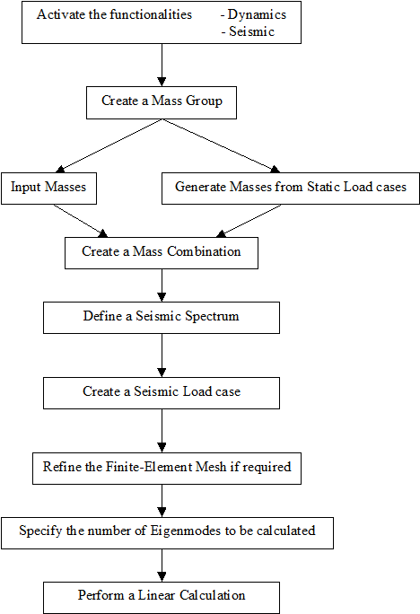
Seismic load calculation in SCIA Engineer
In SCIA Engineer, a Seismic Load can be defined after creating a Combination of Mass Groups. This implies that the steps used to perform a Free Vibration calculation still apply here and are expanded by the properties of the Seismic Load.
The response spectra can be defined either using the provided spectrum generators, or manually as a list of frequency/acceleration pairs(which can also be easily copied from an external spreadsheet). The generators are available for many seismic design standards.
Calculation protocol of free vibration in SCIA Engineer
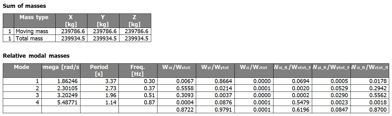
The Eigenfrequency calculation protocol is listed for each computed combination of mass groups. It contains the following information:
Sum of masses - X, Y, Z
Moving mass: total mass taken into account in the modal analysis for each global direction
Total mass: total mass in the model for each global direction
Relative modal masses
Table that contains information about each computed eigenmode
Mode
# of eigenmode
Omega
Pulsation of eigenmode, aka natural circular frequency, usually given in [rad/s]
Period
Period of the eigenmode, usually given in [s]

Freq.
Frequency of the eigenmode, usually given in [Hz]

Wxi/Wxtot, Wyi/Wytot, Wzi/Wztot
Effective modal mass ratios for translation in X,Y,Z direction, aka relative modal mass or participation mass ratio in X,Y,Z direction, given as a ratio of the total mass of the structure taken into account in the same direction; see mrel,(j) in the theoretical background section above
Wxi_R/Wxtot_R, Wyi_R/Wytot_R, Wzi_R/Wztot_R
Effective modal mass ratios for rotation around the mass centre of the structure and around an axis parallel to the X,Y,Z global axis, aka relative modal mass inertia around X,Y,Z axis, given as a ratio of the total mass inertia around the same axis
Note: the last row of the table gives the cumulated participation mass ratio of all computed eigenmodes
Calculation protocol of seismic load cases in SCIA Engineer
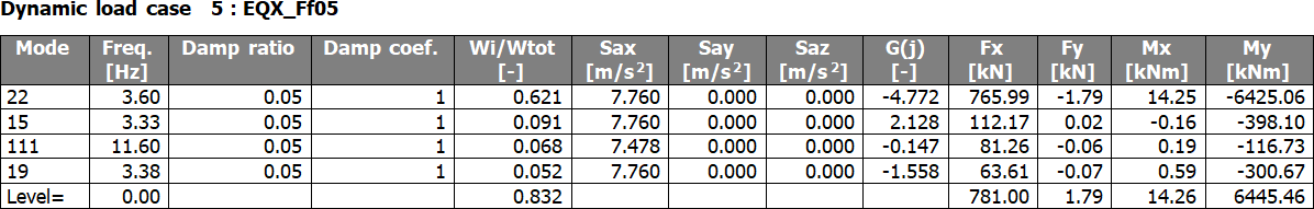
The Seismic calculation protocol is listed for each computed seismic load case. It contains the following information:
Mode
# of eigenmode
Freq.
Frequency of the eigenmode, usually given in [Hz]
Damp ratio
Relative damping ratio  for the considered eigenmode
Damp coef
Damping coefficient  for the considered eigenmode

Wi/Wtot
Effective modal mass ratios for translation in the direction of the seismic action, aka relative modal mass or participation mass ratio, given as a ratio of the total mass of the structure taken into account in the same direction; see mrel,(j) in the theoretical background section above
Sax, Say, Saz
Spectral acceleration in direction X,Y,Z corresponding to the considered eigenmode
G(j)
Total mode coefficient for the considered eigenmode; see theoretical background section above
Fx, Fy
Seismic force in X,Y direction, aka base shear; see Modal lateral force in theoretical background section above
Note: the last row of the table gives the cumulated forces for all computed eigenmodes (modal superposition)
Mx, My
Overturning moment around X,Y axis at the reference level; see Modal overturning moment in theoretical background section above
Note: the last row of the table gives the cumulated overturning moments for all computed eigenmodes (modal superposition)
Level=
Reference level for the calculation of overturning moments