Advanced cable analysis
This document gives an overview of the usage and theoretical background for cable members. The following aspects are presented:
- Calculation of the initial geometry of a cable member
- Finite element mesh of a cable member
- Initial tension - taken into account or not
- Linear and nonlinear behaviour
- Output of deformations - specific settings for cables
- Example: influence of the initial tension
- why it is not possible to have internal nodes on a cable member
- apparent discrepancies in result output (displacements) - differences between the various displacement output options
Cable nonlinearity
There is an essential difference between cable nonlinearity and other types of local member nonlinearities - it affects the model and the analysis in several ways, which are:
- the initial geometry of the cable and, as a consequence, its finite element mesh
- the initial tension of the cable
- both linear and nonlinear behaviours of the element
Other types of local member nonlinearity affect only one aspect: press-only, tension-only, limit force and gap types only affect the nonlinear behaviour; initial stress only affect the initial stress level of the considered member.
Initial geometry
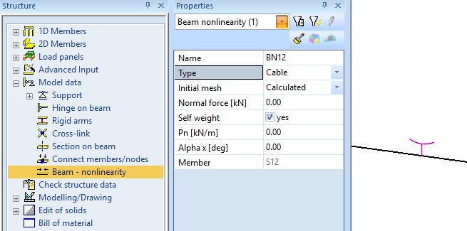
A cable member is always input as a segment defined by its two end-nodes.
Its initial geometry (or mesh) can be either straight or calculated (see cable nonlinearity properties above).
In case Initial mesh = straight, the initial geometry is the same segment are defined by the user.
In case Initial mesh = calculated, the initial geometry is curved and defined according to the following principles:
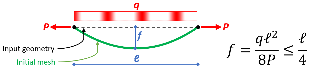
The general idea is, that the initial geometry of the cable is such that the tension in the cable is equal to the defined P tension when the transverse load q is applied to it.
- the initial curvature is calculated based on the simplified formula above
- the curvature is defined by the deflection of the cable in its middle
- the considered transverse load q for the calculation of f may include
- the component of the self-weight of the cable perpendicular to the input segment (self-weight option in the cable settings)
- an arbitrary load perpendicular to the input segment (Pn value in the cable settings)
- the typical initial curvature of the cable is typically defined in a vertical plane; however, a horizontal curvature component may be introduced by means of the Alpha x angle, which defines a rotation of the Pn load around the axis of the input segment
- the approached initial geometry of the cable for the analysis is taken as an arc of circle defined by the end-nodes of the input geometry and the calculated initial deflection at mid-span. In essence, only the initial length of the cable is relevant. The final geometry of the cable, after nonlinear analysis, is the exact equilibrium shape.
The approached initial geometry is sufficiently accurate when the initial deflection is significantly smaller than the span length (e.g. L / f > 10)
In case the tension P is not defined (i.e. set equal to zero), the initial curvature cannot be calculated, as it would lead to a division by zero. In such as case, f is taken equal to zero and the initial geometry is taken as astraight segment.
Initial mesh
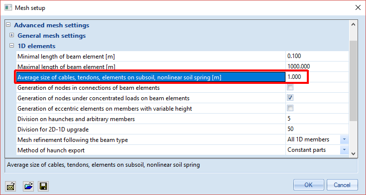
In order to take the correct initial geometry of the cable into account in the analysis, the finite element mesh of the cable must be sufficiently refined. The mesh size for cable members can be configured in the mesh settings. Regardless of their length, cable members always have at least one intermediate node.
Initial tension
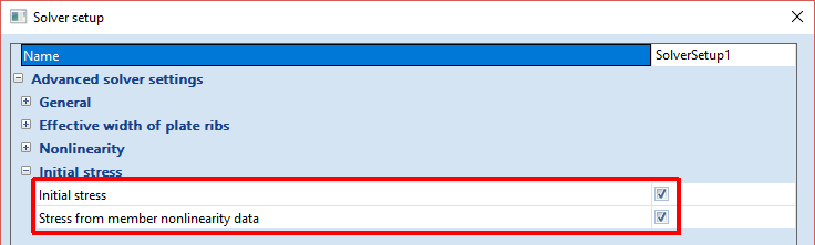
The normal force value that is defined in the cable nonlinearity settings is used as initial stress for the member in a nonlinear analysis if - and only if - initial stresses from member nonlinearity data are enabled in the solver setup.
Linear and nonlinear behaviour
This is certainly the most obvious part of cable nonlinearity. A cable member:
- is a tension-only member in nonlinear analysis
- has no bending nor shear stiffness (actually, a very, very small stiffness) in both linear and nonlinear analysis; as a consequence the resistance of a cable to transverse loading relies strictly on mobilizing its axial stiffness through a large displacement analysis (3rd order, typically Newton-Raphson)
Because of the absence of bending and shear stiffness, cable members may not be used in a linear analysis, as they invariably lead to extremely large displacements or structural instability. A 3rd order nonlinear analysis is required for them to be considered correctly.
Output of deformations
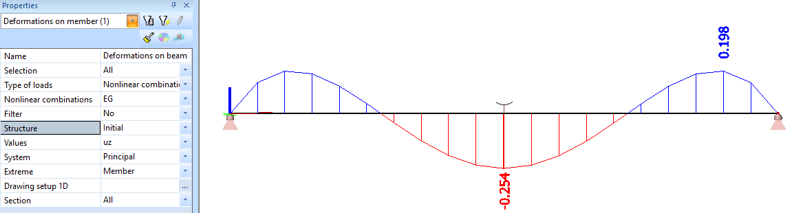
The setting Structure for output of deformations on beams is particularly useful for cable members. The screenshots below show the deformations of a cable with calculated initial curvature for a quite low value of initial tension.
With Structure = Initial, the calculated deformations are displayed on the input geometry of the member (straight segment). In essence, the computed deformations show the difference between the initial, approximated mesh (an arc of circle) and the final, exact equilibrium shape (catenary).
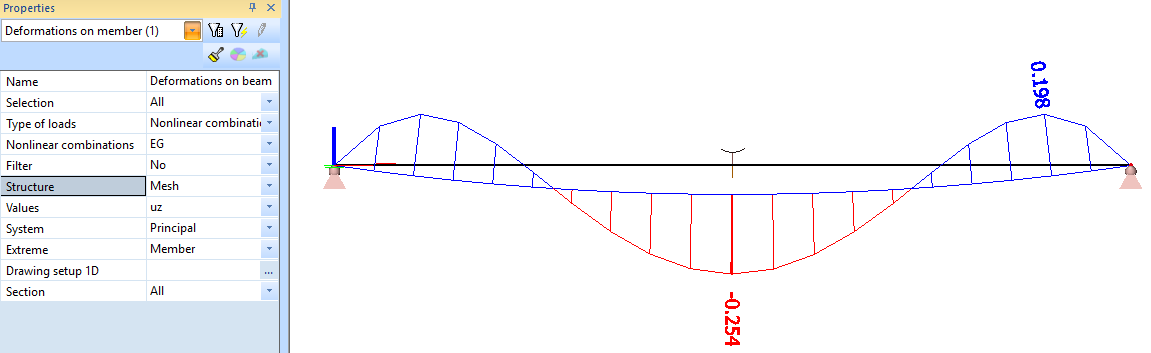
With Structure = Mesh, the diagram of deformations is drawn along the initial mesh of the structure, which corresponds to the computed initial curved shape of the cable.
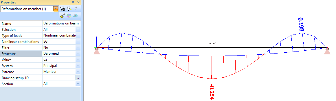
With Structure = Deformed, the diaphragm of deformations is drawn along the final, deformed mesh of the structure, which corresponds to the final equilibrium shape of the cable. In this example, the output is almost identical to the Mesh output (no visible difference), because the deformation values are very small in comparison with the initial deflection.
With Structure = Global deformation, the diagram is drawn along the input geometry of the member (straight segment) and the values are the difference between the input geometry and the final equilibrium shape of the cable. In other words, global deformations are the sum of the initial deflection of the cable plus the deflection due to the applied loads.
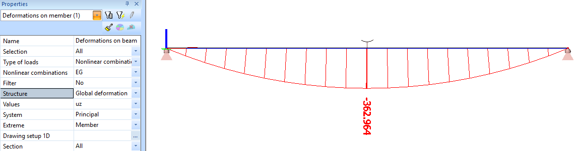
Numerical values for this example:
- self-weight of the cable q = 8.705 N/m
- span length L = 10 m
- initial tension P = 0.3 kN
- initial deflection f = 8.705 * 102 / 8 / 0.3 = 362.710 mm
- deflection under self-weight uz = 0.254 mm
- global deflection under self-weight uz,tot = 362.710 + 0.254 = 362.964 mm
Influence of the initial tension
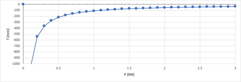
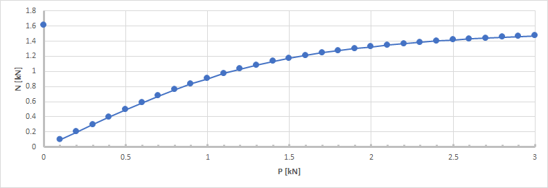
The initial tension has a major impact on the behaviour of the cable as it influences both the initial geometry of the cable and its initial stress level. The following charts show the variation of the initial curvature f and the deflection and normal force of the cable under self-weight alone. The input data of the cable is the same as the example in the previous paragraph. Only the initial tension P varies.
The initial deflection f (initial curvature) decreases asymptotically to zero as the tension increases. When P decreases towards zero, the initial deflection f increases asymptotically to the infinite. Please note the singularity point for P=0, due to the special handling of that case.
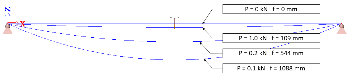
The first picture below shows the initial geometry (mesh, in blue) and the final equilibrium shape (in red) for the extreme case with P = 0.001 kN. In theory, it would correspond to f = 108.8 m, however, SCIA Engineer limits the value of f to L / 4, leading in this case to f = 10 / 4 = 2.5 m. The second picture gives the deflection for the same case, i.e. the difference between the initial shape and the equilibrium shape.
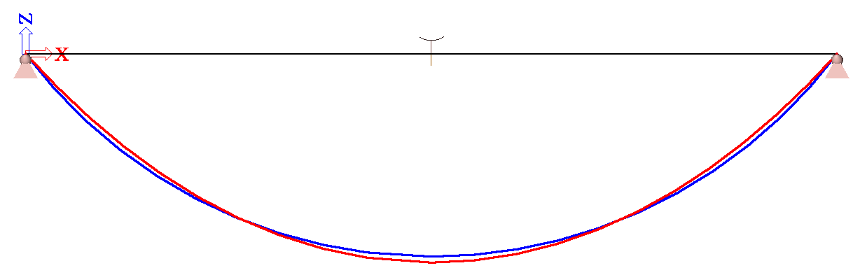

Reminder: the initial geometry of a cable member is an arc of circle. The final equilibrium shape under self-weight is a catenary.
When initial stresses from member nonlinearity data are enabled in the solver setup, the deflection under self-weight tends to zero when the initial tension increases. The limit case with P=0 exhibits a significantly higher deflection, as it starts off from a straight cable without prestressing. All other cases start off from a curved cable geometry which is very close to the final equilibrium shape.
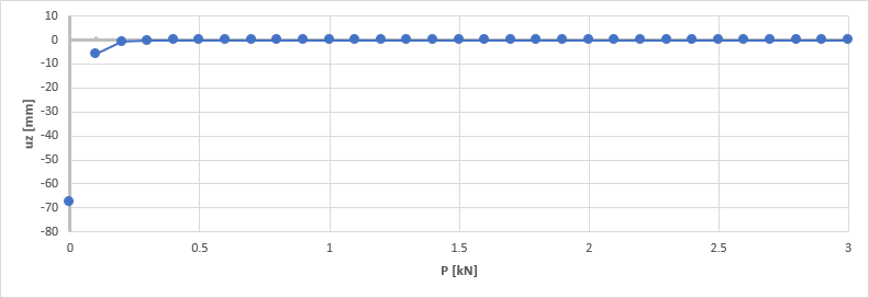
As a consequence, the global deformation (i.e. initial deflection + deflection due to self-weight, grey curve) is almost identical to the initial deflection (blue curve), except for the limit case P=0.
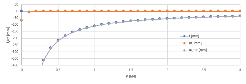
Looking at global deformation results, it appears that the deflection for P=0 is smaller than for small non-zero values of P. This apparently makes no sense, as common sense leads to think, that prestressing should reduce the deflection. It is, however, a wrong perception in this particular case. The observed discrepancy is due to the fact, that the P=0 case is based on a straight initial shape of the cable and all non-zero P cases are based on a curved initial shape. Therefore, global deformations cannot be compared for those cases.
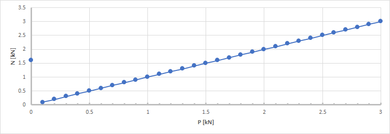
The final value of the normal force in the cable is almost identical to the configured initial tension. The small differences are due to two approximations in the process:
- the initial shape of the finite element mesh is an arc of circle, which is slightly different from the theoretical catenary shape; it results, that the actual length of the cable in the model is not totally accurate
- the calculation of f is based on the assumption of a 2nd order parabola shape, which is again slightly different from the ideal catenary; the inaccuracy linked to that aspect decreases drastically as P increases
Again, the case P=0 is particular. The explanation of that case will appear more clearly further below.
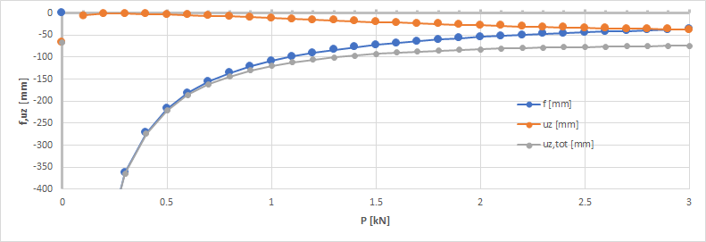
When initial stresses from member nonlinearity data are disabled in the solver setup, the deflection progressively increases as P increases. This is because the initial shape of the cable is completely different from its equilibrium shape.The elongation of the cable is normally compensated by the initial tension, which is not the case here. The straighter the initial shape, the more the (uncompensated) elongation affects the equilibrium shape.
P=0 is no longer a singularity, special case. Remember, that P=0 is analyzed with f=0. When P increases, f progressively decreases to zero too. As no initial tension is applied to the cable, a very large value of P leads to an almost straight initial shape of the cable. If, additionally, no initial tension is considered,it corresponds to the limit case P=0.
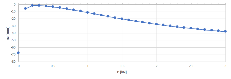
As P increases, f tends to zero and both uz and uz,tot tend to the deflection of a perfectly straight cable (case P=0).
As P increases, the normal force in the cable tends to the tension of a perfectly straight, non-prestressed cable (case P=0).
Frequently asked questions
Why is not possible to add internal nodes on a cable member
The input geometry of a cable must be strictly defined by only two end nodes, because the initial shape is then calculated as a curve between those two point. Intermediate points are not supported by the calculation method.
If intermediate points are necessary, the cable member must be split into more members.
Why does a cable with zero initial tension have smaller deflection than with a small non-zero initial tension
The case with P=0 is an exception. P=0 would lead to a division by zero, which is why it is not possible to calculate a value of initial deflection in that case. SCIA Engineer considers the cable as straight (f=0) in that case. Because of that, the deformed shape of the cable is usually very different from the equilibrium shape and, as a consequence, the value of global deformation is high. For more details, see the notes about the P=0 case in the text above.
Practical tip: do not use initial tension = 0 for a cable with calculated initial mesh.