Friction support
Definition, application
Support nonlinearity is nonlinear functionality which can be apply on any type of supports. These features can simulate special nonlinear behaviour of supports. For taken into account it is necessary to perform nonlinear analysis.
Where to find it
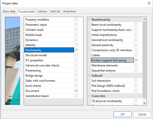
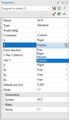
In project data dialog in part 'Functionality' it is necessary to switch ON 'Friction support/Soil spring'. After that in support properties there are several new possibilities which can be set for any degree of freedom.
When inserted into the model, a friction support (friction defined in Y and Z direction) is marked with the following symbol (remember that in order to see the symbol, view parameters must be adjusted to show model data).

Possibilities
|
From reaction |
The user may select the reaction that defines the force pushing against the support. |
|
C flex |
Stiffness of the support. This stiffness applies ONLY until the friction force is exceeded. |
|
mju |
Coefficient of friction. If friction of X / Y / Z or XY / XZ / YZ type is selected, one mju value must be input. If friction of X+Y / X+Z / Y+Z type is selected, two mju values must be input. |
|
Independent |
If simple friction (X, Y, Z) is defined in two directions, this option is available. It specifies that friction in one direction is independent on the friction in the other direction. |
From reaction


Note: Friction can be input in one or two directions. It is not possible to define friction in all three direction otherwise the "thrust" could not determined.
Note: Composed friction (e.g. YZ or Y+Z) can be input in one direction only.
Note: Option Independent friction is available ONLY if simple friction (X, Y, Z) is defined in two directions.
Limitations
Supported members
Table of supports, for which it is possible to set nonlinearity in project.
| Type of support |
Example
Let’s assume a plane XY and a support that can slide on it in any direction with a friction.
|
X |
friction |
|
C flex x |
1E5 |
|
mju x |
0.20 |
|
from reaction |
Z |
|
Y |
friction |
|
C flex y |
1E5 |
|
mju y |
0.55 |
|
from reaction |
Z |
|
Z |
rigid (or press only) |
|
Independent friction |
YES |
Let’s assume a pipe in a borehole in X-direction.
|
X |
friction |
|
C flex x |
1E5 |
|
mju x |
0.20 |
|
from reaction |
YZ |
|
Y |
flexible |
|
stiff y |
5E5 |
|
Z |
flexible |
|
stiff z |
3.5E6 |