Bow imperfections - Theoretical background
This article describes how bow imperfections are taken into account in the nonlinear analysis in SCIA Engineer.
Bow imperfections are taken into account only in nonlinear analysis in SCIA Engineer. Bow imperfections do not affect other types of calculation, such as linear or stability analysis.
Principles: notional loads
Consider a 1D member, typically a column.
The initial bow imperfection e0,d is given, usually defined by design standards.
The axial force NEd is supposed known and constant.
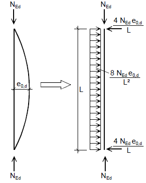
The bow imperfection is introduced in the analysis by applying a set of self-balanced transversal loads on the 1D member, which produce the same bending moment as the eccentricity of the axial force due to the supposed initial imperfection.
The moment induced by the imperfection is

The moment induced by a distributed uniform load on a simply supported beam is the well-known

Combining the previous two equations, the notional distributed load for the bow imperfection is

Additionally, concentrated forces are applied in the opposite direction at each end of the member to ensure that the total applied load is zero

The method of notional loads for bow imperfections is proposed in several design standard. Among them, see Eurocode EC-EN 1993-1-1:2005 clause 5.3.2(7) and figure 5.4.
Implementation in SCIA Engineer
When bow imperfections are used in a nonlinear analysis, the following steps are taken:
- first iteration of the nonlinear analysis, which is, in essence, a linear analysis, without imperfections
- for each member where a bow imperfection must be applied, the direction of the curvature is obtained from the results of the first iteration; it is given by the sign of the relative deformation according to the member-LCS (Y or Z) at the mid-point of the span; the value of the normal force is taken at the same point

- the notional distributed loads are applied in the same direction as the obtained curvature, so that the bow imperfection will increase the moments due to the 1st order effects; concentrated end loads are also applied, in order to keep the overall balance of the system; the notional loads are applied in the background, they do not appear directly in SCIA Engineer
- the nonlinear analysis continues (further iterations)
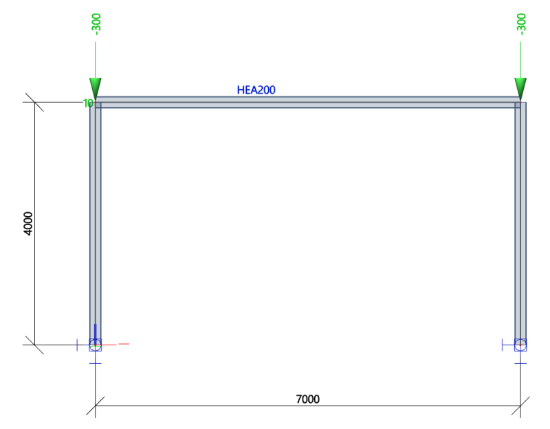
Example 1: frame with point loads
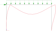
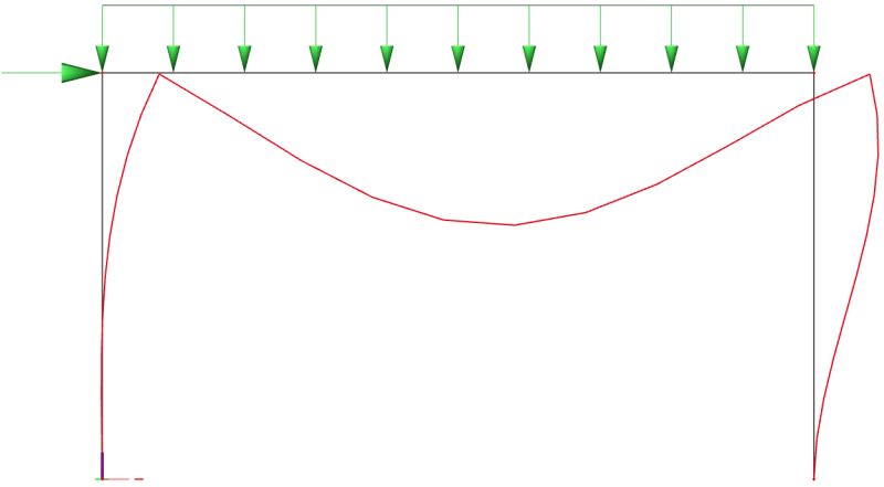
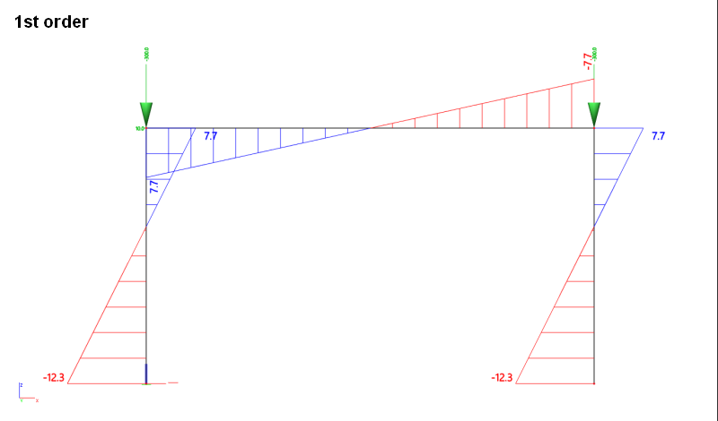
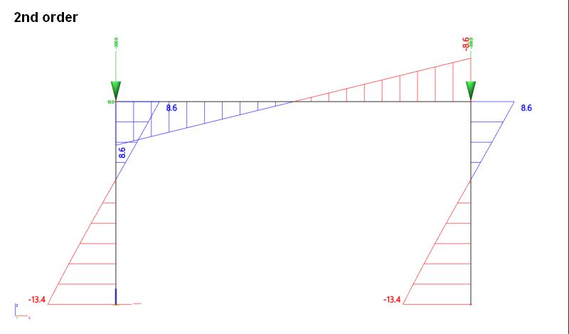
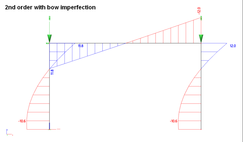
This example is a simple frame with fixed supports. 2 vertical 300 kN point loads are applied at the top of the columns, plus one horizontal 10 kN load at the left end of the beam. Bending moments are presented for 1st order analysis, 2nd order analysis with and without bow imperfection (L/200 = 20 mm for the columns).
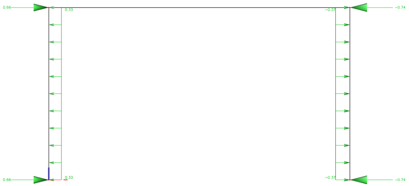
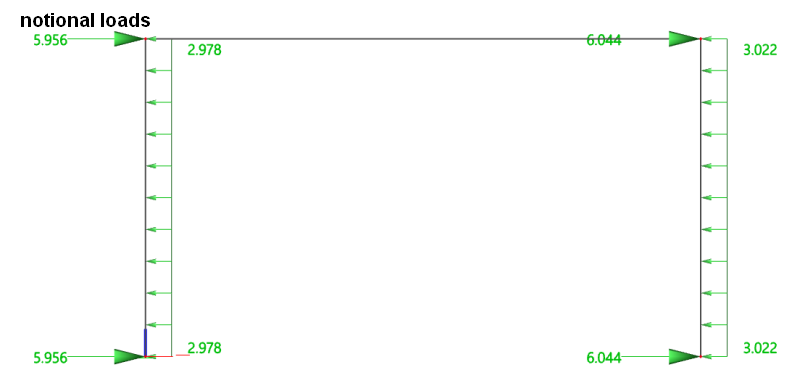
The axial forces in the columns are -297.8 kN and -302.2 kN respectively. The columns are 4 m high and the imperfection is defined as L/200, which corresponds to 20 mm. This leads for the left and right column, respectively, to the following notional loads


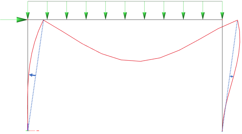
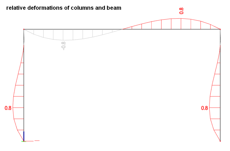
The 1st order relative deformations of 1D members show the direction in which the notional loads are to be applied.

Special case: no 1st order curvature
It can happen, mostly in simplified, academic cases, that some members have no 1st order curvature, which means, that the algorithm described previously has no mean to determine the most unfavourable direction for the bow imperfection.
In such a case, the bow imperfection is applied to the considered member in an arbitrary direction, depending on the orientation of the LCS of the member.However, in case there is a continuity of a member, the imperfection should not be applied in the same direction for all spans, but rather alternate.
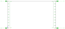
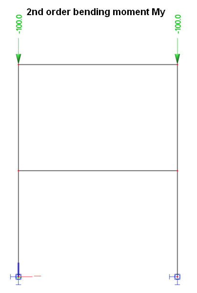
Consider, for instance, the following example. The perfect symmetry of the structure, combined with the symmetrical nodal loading, induces pure shortening of the columns, without any bending nor lateral displacement. Both columns remain perfectly straight, thus providing no indication of the unfavourable direction for bow imperfections.
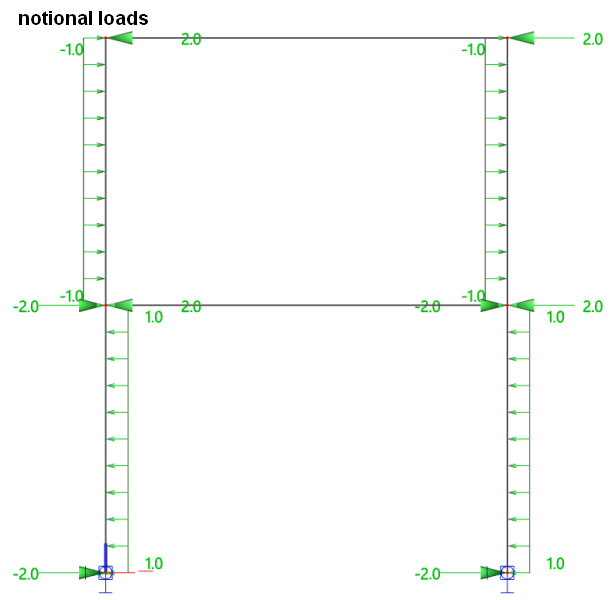
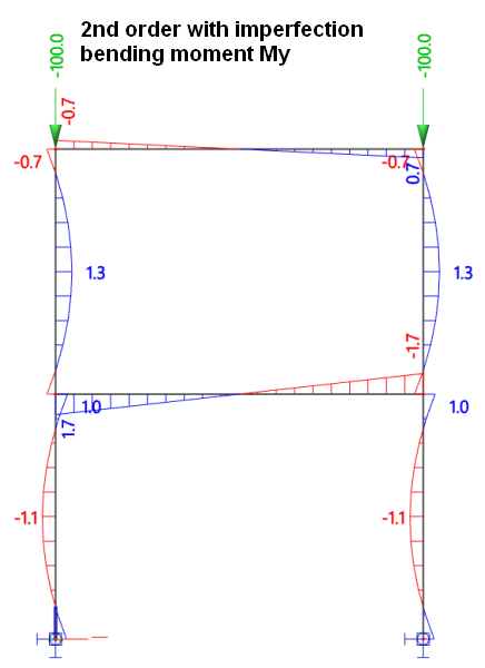
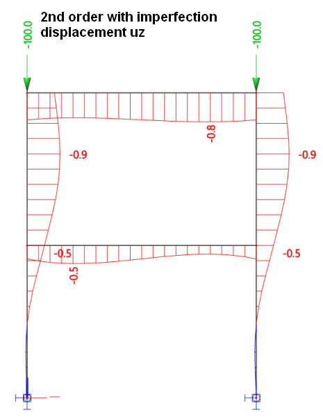
In that case, the program applies the bow imperfection arbitrarily on the first span and then alternates on the following spans (storeys in that case).
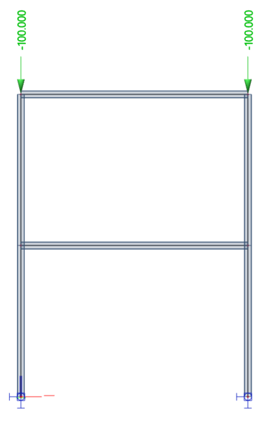
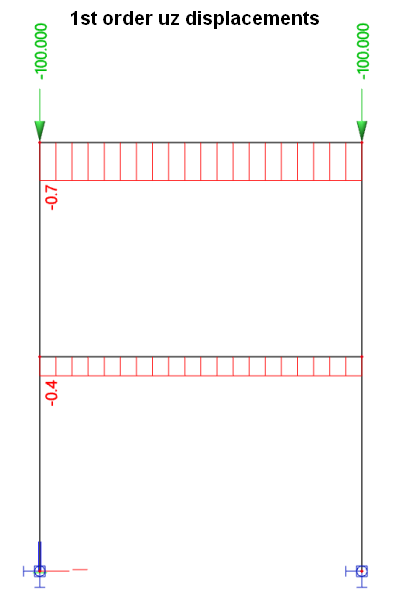
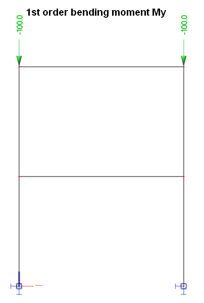
For such a system, there is neither bending moment nor lateral displacement in neither 1st nor 2nd order analysis, unless some imperfection is introduced.
Constructions with perfect symmetry of both the structure and the loading are extremely rare in reality. Such a use case is much more likely to occur in academic examples or in benchmarks.