Composite Analysis Model - Theoretical background
This chapter describes the theoretical background that is used in the composite analysis model (CAM) of SCIA Engineer. Some aspects of it are general while others focus only on the methods that are implemented in SCIA Engineer. Unless mentioned otherwise, all principles that are presented here are code independent.
General principles
The Composite Analysis Model (CAM) of SCIA Engineer is based on a standard 3D modelization of the structure. Fundamentally, a composite deck with beams is modelled as a plate with eccentric ribs. The plate represents the composite deck, which is, in itself, a composite structural element made of a profiled steel sheeting with a concrete topping. The steel beams are represented by eccentric or non-eccentric 1D members, i.e. plate ribs, connected to the plate.
Based on the input, SCIA Engineer offers essentially two methods for the analysis of composite and metal decks: a diaphragm approach and a standard FEM approach. The diaphragm approach offers the advantage that it is generally more computationally efficient and provides a more idealized distribution of load to the composite plate ribs. The standard FEM approach offers the advantage of providing more accurate results.
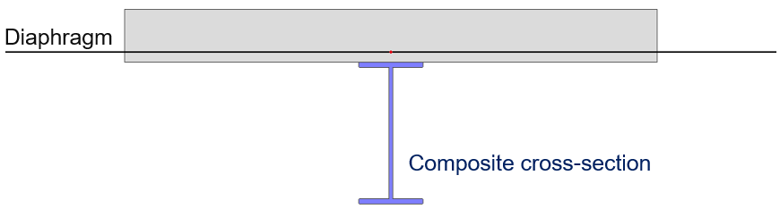
In the conventional approach, the analysis model consists of a grid of composite beams, combined with a diaphragm.
- the loads are transmitted from the floor surface to the beams by means of a load panel;
- the out-of-plane stiffness of the deck is not part of the overall analysis model of the structure;
- the in-plane stiffness of the deck, depending on its properties and geometry, is taken into account as a rigid, semi-rigid or flexible diaphragm;
- the influence of the participating width of the deck is fully taken into account in the properties of the composite cross-section of the beams.
Additionally, the composite analysis model of SCIA Engineer offers a more accurate approach, where the deck is modelled as a finite element plate, with its real stiffness properties. The beams are modelled as plate ribs, with or without eccentricity depending on the case.
- the loads are applied directly to the FE deck and are transmitted through the structure via FEM analysis;
- both out-of-plane and in-plane stiffness components of the deck are taken into account directly in the FEM analysis;
- depending on the selected case, the influence of the participating width of the deck is taken into account via the FEM analysis or via modified properties of the cross-section of the composite beams.
See a few application examples:
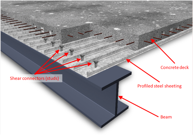
Composite deck
In the context of the CAM, the deck is the plate that carries the loads and transfers them to the beams. This section describes the principle of analysis of that plate only. The behaviour of composite beams will be discussed in another section.
The principle described here for the analysis of the deck is used directly when the deck is analyzed as a FE plate, as well as for the in-plane stiffness in the case of a semi-rigid diaphragm. In the case of rigid and flexible diaphragms, the real stiffness of the deck is not taken into account. However, in all cases, the orthotropic properties of the deck are taken into account when determining the influence of the participating width in the modified properties of the cross-section of composite beams.
There are composite decks and metal decks. A composite deck has two layers: a profiled steel sheeting and a concrete topping, reinforced or not. A metal deck has only one layer, i.e. the profiled steel sheeting, and is mostly used for light-weight roofs.
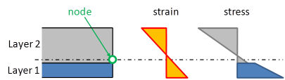
A composite deck is modelled as a multi-layered plate. Each layer has orthotropic properties and the eccentricity of each layer is taken into account.
The interaction of the layers is considered as a perfect bond, i.e. without any slip between the layers (concrete and steel sheeting). The strains are determined from the displacements and rotations at the nodes of the finite element mesh.
The assumption of perfect bond is reasonable for the longitudinal behaviour of the composite deck, i.e. in the direction parallel to the corrugation. In the direction perpendicular to the corrugation, this is less obvious, since the profiled sheeting properties are first determined independently. In the composite deck, the “accordion” behaviour of the sheeting will be stabilized by the concrete in case the sheeting is in compression. However, the stiffness of the sheeting in that direction is very low and will hardly influence the behaviour of the composite deck. That approximation is therefore acceptable.
Please note, that the concrete-steel bond applies only in final stage. In construction stage, only the stiffness of the steel sheeting is taken into account (see Construction stages for composite analysis below).
A detailed description of the calculation of the stiffness of the composite and metal decks is given in the chapter Composite Deck Analysis Model. See also the chapter about element types.
Composite beam
The pictures below show the analysis model used for composite beams, not the real structure.
In the context of composite structures, there are currently 3 possible types of behaviour for plate ribs in SCIA Engineer:
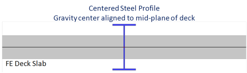
with standard composite action
in this case, the composite beam is modelled as a plate rib without eccentricity. The shear connection may be total or partial. In order to consider the composite action, the stiffness of the beam is adjusted to take into account the effect of the eccentricity and of the participating deck width. In case the deck is taken into account as FE plate, internal forces for the composite checks are obtained by integrating the calculated stresses in both the steel beam and the deck.
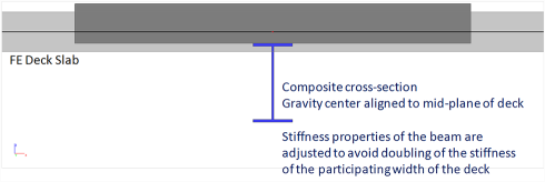
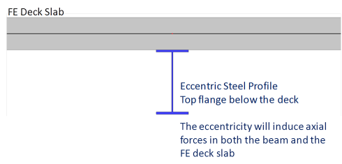
with advanced composite action
in this case, the composite beam is modelled as an eccentric plate rib (real eccentricity). This model is used only when the deck is modelled as a FE plate. When "advanced composite action" is selected and the linked 2D member is not a FE plate (e.g. a diaphragm), then "standard composite action" is used instead. Only a total shear connection is possible in this case. In this configuration, an axial force will appear in the beam and membrane forces will appear in the deck. The diffusion of the membrane forces in the deck (shear lag) will be automatically calculated by the FE model of the deck. The internal forces for the composite checks will be obtained by integrating the obtained stresses in both the steel beam and the deck (within the deck participating width).
without composite action
this is used to represent beams that are connected to the deck without shear connectors, i.e. the deck is just lying on the beam and may, in theory, slip on the beam. There is no composite action when using this option. This is modelled by a plate rib without eccentricity because the bending stiffness of such a beam is equal to the sum of the bending stiffness of the steel beam and the bending stiffness of the participating width of the deck. There is no lever arm effect of axial forces, as there would be in a beam with composite action.
A beam without composite action is not a non-composite beam. It is a composite beam without composite action.
The pictures above show the analysis model used for composite beams, not the real structure.
The selected model for the deck (FE plate or diaphragm) affects the way the modified properties of the cross-section of the composite beams are determined. In the case of a diaphragm, the conventional approach applies mostly, as the stiffness of the deck is not taken into account directly by the analysis model in most cases. On the other hand, in the case of a FE plate, the stiffness values of the modified composite cross-section must be altered to avoid the stiffness of the deck being taken into account twice.
A detailed description of the calculation of the stiffness of a composite beam is given in the chapter Composite Beam Analysis Model.
Construction stages for composite analysis
Construction stages must be taken into account in the analysis of composite structures for two main reasons:
-
the profiled steel sheeting is used as a formwork for the concrete topping, hence it alone must support the weight of concrete
- the behaviours of steel and concrete are fundamentally different: stiffness, creep
In the general case, construction stages are taken into account in a simplified way, by calculating each load case in the stage corresponding to its assumptions. The results (displacements, internal forces…) can then be combined in load case combinations.
In the standard composite analysis model, 3 stages are defined for the entire structure. There is no such thing as stages for casting of concrete or staged building of the steel structure. It is, however, planned that this will be supported in a later version.
Construction stage
in this stage, only the steel of the composite decks is enabled. Concrete has no stiffness and its self weight is hence carried by the steel structure (profiled steel sheeting and steel beams). By default, only the self weight load case is assigned to this stage.
Final stage, long term
in this stage, the composite decks are enabled. The concrete stiffness is reduced to take into account the effect of creep under long term loads. By default, all permanent load cases, except self weight, are assigned to this stage.
Final stage, short term
in this stage, the composite decks are enabled. The nominal concrete stiffness is used, for use under short term loading. By default, all variable load cases are assigned to this stage.
Creep
Creep is taken into account using a reduced value of the elasticity modulus for concrete in the final stage, long term. The creep coefficient is defined in the composite setup for the entire structure and applied to all composite decks.
During the calculation of the orthotropy matrices, adjusted values of Ec and Gc are used in each stage for concrete:


where Ec0 (Gc0) is the E-modulus (G-modulus) of concrete from the material library.

where  is the creep factor defined in composite setup.
Creep can be optionally disabled, in which case load cases from the long term stage are moved to the short term stage during the analysis.
Propping
It is assumed by default that the weight of concrete is carried solely by the steel structure. It can optionally be assumed, that the steel structure is entirely propped during the casting of concrete. The propping is then removed after the concrete has hardened.
This can be taken into account by moving all load cases from the construction stage to the final stage (long term or short term, depending on creep settings).
Partial self-weight of composite decks
Several codes require, that the additional weight of water during casting of concrete is taken into account in the composite construction stage. To achieve this, the CAM allows to split the self-weight of composite decks in 3 parts. When the appropriate option is enabled in the composite setup, for any defined self-weight load case,SCIA Engineergenerates two additional load cases. When that option is disabled, only the standard self-weight calculation is carried out, without partial self-weight calculation. The content of the partial self-weight load cases is as follows:
| partial self-weight load case for dry concrete | self-weight of dry concrete of composite decks, using its standard density (typically 2500 kg/m3, defined in the material library) |
| partial self-weight load case for fresh concrete | self-weight of fresh concrete of composite decks, using it fresh density, defined in the material library (this setting is specific for concrete materials) |
| standard self-weight load case | self-weight of the rest of the structure, i.e. the profiled steel sheeting of composite decks, as well as all other members of the structure |
Combining the load cases
Due to a common misunderstanding about composite stages and the load case combinations corresponding to each stage, a common mistake is to only include final stage load cases in final stage checks.
Construction stage checks and construction load case combinations are straight forward. All relevant load cases are applied in the construction stage and used in the corresponding stage.
Final stage checks - long term or short term – are less intuitive. Each load case must be assigned to the stage corresponding to the time of application of the loads. Typically, the load cases applied to each stage are the following:
| Construction stage |
actions applied before the composite action can be mobilized
|
| Final stage, long term |
long term actions, applied when concrete has hardened and composite action can be mobilized; their effect is affected by creep
|
| Final stage, short term |
short term actions, applied when concrete has hardened and composite action can be mobilized; their effect is not affected by creep
|
Once the load cases have been computed, they can be combined. To obtain the correct deflections and internal forces, the load case combinations typically contain, for typical checks:
| Combination for... | Load cases | Computed in... |
|---|---|---|
| Construction stage checks |
partial self-weight of non-composite parts |
construction stage |
|
|
||
|
|
||
| Evaluation of long term deflections |
partial self-weight of non-composite parts |
construction stage |
| partial self-weight of dry concrete | ||
| permanent load cases | final stage, long term | |
| permanent part of variable load cases | ||
| Final stage checks |
partial self-weight of non-composite parts |
construction stage |
| partial self-weight of dry concrete | ||
| permanent load cases | final stage, long term | |
| variable load cases | final stage, short term |
Load case combinations for final stage checks, including long term deflection checks, contain load cases from construction stage and final stages.
Nonlinear, stability & dynamic analysis of composite structures
In linear static analysis, composite stages may be simply taken into account by calculating each load case separately with the appropriate stiffness values. Internal forces and displacements are then combined after the analysis by simple summation.
In the case of nonlinear and stability analysis, load cases are combined beforehand and the calculation is run in one pass, with a single set of stiffness values. In dynamic analysis, the modal behaviour of the structure is obtained on the basis of masses and, again, a single set of stiffness values. Because of that constraint, a reference composite stage must be selected to determine the appropriate set of stiffness values.
Composite nonlinear analysis
In the case of nonlinear analysis, the user may either select manually the reference composite stage or let the program select it automatically. The latter is the default behaviour.
Automatic selection is based on the principle, that the last applied load case, in time, is relevant. For each nonlinear combination,SCIA Engineer considers the composite stage defined for each load case in that combination.
| If the load cases in the combination are in composite stage... | Then the nonlinear combination is considered in composite stage... |
||
| Construction | Final, long term | Final, short term | |
| X | Construction | ||
| (X) | X | Final, long term | |
| (X) | (X) | X | Final, short term |
Composite stability analysis
In the case of stability analysis, only automatic selection is possible (see description above).
Composite dynamic analysis
In the case of dynamic analysis, composite final stage, short term, is always used.The reason for that is, that dynamic actions are typically applied after completion of the construction.
- Vibration analysis: serviceability checks on the completed structure
- Seismic analysis: structural safety under seismic actions
Such checks are very rarely performed during construction stage.