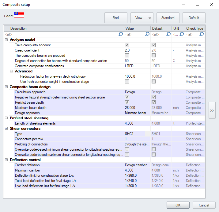
| Composite beam design |
| Calculation approach |
defines how the beam and shear connectors are handled when the composite beam design/check is carried out:
check:, the program checks the members for strength and serviceability at construction and final stages using the number of shear studs input in Number of rows (between points of min and max moment). Under this approach, the degree of composite action input in Degree of connection for beams with standard composite action should be estimated. However, the actual degree of composite action for each member based on the number of studs is calculated during the calculation. The model can be updated with these actual values by selecting Apply design proposals to model after running the calculation.
design:, an optimum cross-section and target degree of composite action are calculated by the program for each cross-section group. The model can be updated with these proposed parameters by selecting Apply design proposals to model after running the calculation.
overridable
|
| Negative flexural strength determined using steel section alone
|
defines whether the reinforcement bars in the deck should be taken into account or not when determining the negative flexural strength of the composite cross-section.
checked/on, the negative flexural strength is determined for the steel section alone.
unchecked/off, the number of studs in each negative moment region will be calculated based on the Target degree of composite action and the negative flexural strength calculated from the plastic stress distribution on the composite section.
Note: When designing composite members, the default setting (checked) may result in a less conservative cross-section if considerable negative moment exists on the member, however, it is often the preferred approach since the alternative approach (determining the negative flexural strength from the plastic stress distribution on the composite section) will calculate the actual number of studs needed in each region of negative moment. This is often impractical since these regions are not clearly defined during the stud installation process.
overridable
|
| Restrict beam depth
|
defines, if the depth of the beam cross-section should be restricted to a given value when optimizing the beam during design.
overridable
|
| Maximum beam depth
|
the maximum depth value of the beam cross-section when optimizing the beam during design.
overridable, only AISC 360-10
|
| Design approach
|
defines the design approach to be used for beam design. Depending on the selected approach, the target degree of composite action is defined as follows and used in both the analysis model and the design:
- Minimize beam size: Design based on member with the least weight. For this option, target degree of composite action will be set to 100% (full).
- Minimize number of studs: Design based on fewest number of studs. For this option, target degree of composite action will be set to 30%
- Balanced: Design based on balanced approach. For this option, target degree of composite action will be set to 55%
- User defined: Design will find section that works with target degree of composite action that the user inputs
overridable, only AISC 360-10
|
| Target degree of composite action
|
defines the target degree of composite action in case of user-defined Design approach. This value is used in both the analysis model and the design.
overridable, only AISC 360-10
|
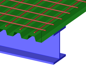
| Profiled steel sheeting |
| Length of sheeting elements |
this value is relevant for the steel code check. It is used to calculate the stabilizing effect of a metal deck on steel beams for lateral torsional buckling. |
| Shear connectors |
| Type |
type of shear connectors to be used for composite action (from shear connectors library).
overridable
|
|
Connectors per row
|
Number of connectors per row.
In the case of the Check calculation approach, the value used for the total number of studs from zero to maximum moment is taken as number of Connectors per row multiplied by the ‘Number or rows’.
In the case of the Design calculation approach, the program will use the value of Connectors per row as the maximum number of rows allowed in the design. The actual number of rows used in the design may be less than the value entered when possible.
overridable
|
|
Number of rows (between points of min & max moment)
|
number of rows of connectors between the points of zero and maximum moment.
Used only for Check calculation approach
overridable, only AISC 360-10
|
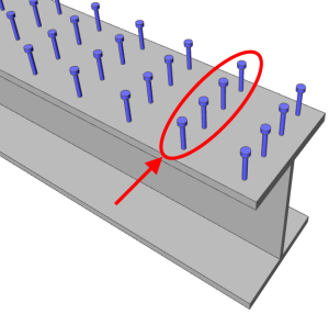
| Welding of connectors |
method of welding of the shear connectors
- through the steel sheeting: the connectors are welded together with the sheeting to the beam
- directly to the beam: the connectors are placed in openings in the sheeting and welded directly to the beam
overridable
|
| Overwrite code-based min shear connector longitudinal spacing requirement |
this setting allows for a specific value to be entered for the minimum shear connector spacing in the longitudinal direction. This value will overwrite the code-based spacing requirement and can be entered below for minimum shear connector longitudinal spacing.
overridable
|
| Overwrite code-based max shear connector longitudinal spacing requirement |
this setting allows for a specific value to be entered for the maximum shear connector spacing in the longitudinal direction. This value will overwrite the code-based spacing requirement and can be entered below for maximum shear connector longitudinal spacing.
overridable
|
| Minimum shear connector longitudinal spacing. |
user defined minimum shear connector longitudinal spacing value.
overridable
|
| Maximum shear connector longitudinal spacing |
user defined maximum shear connector longitudinal spacing value.
overridable
|
| Slab reinforcement |
| Material |
steel material for the reinforcement in the concrete of composite decks.
overridable
|
| Longitudinal |
Bar diameter, bar spacing and concrete cover of reinforcement bars in the slab parallel to the beam
overridable
|
| Transverse |
Bar diameter and bar spacing of reinforcement bars in the slab perpendicular to the beam
overridable
|
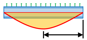
| Deflections |
|
Camber definition

|
type of definition of the camber for composite beams, taken into account in deflection checks or design:
- Design camber: the required camber value is calculated by the program
- No camber: no camber is taken into account
- Input camber (absolute): user defined value of camber, as a length
- Input camber (relative): user defined value of camber, as a fraction of the span length
This setting can be overridden in the composite beam data.
overridable
|
|
Maximum Camber
|
maximum allowed value of camber, used when the required camber is calculated by the program.
overridable
|
| Camber value |
camber value for type absolute, defined as a fixed length
overridable
|
| Camber value L/x |
camber value for type relative, defined as a ratio of the span length, e.g. L/200
overridable
|
| Limit deflection for construction stage |
limit allowable deflection for deflection check in construction stage, defined as a ratio of the span length
overridable
|
| Limit total deflection in final stage |
limit allowable deflection for total deflection check in final stage, defined as a ratio of the span length
overridable
|
| Limit permanent, long term deflection |
limit allowable deflection for permanent deflection check in final stage, defined as a ratio of the span length
overridable
|