Tips & tricks
Internal forces in Result tree
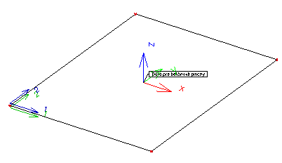
It is possible to check internal forces directly in Results through Member 2D – Internal Forces item. Here, the user can also view the design magnitudes, if attribute Type of the force is set to Elementary design magnitudes.
The Elementary design magnitudes in tree Results are determined differently than in the Concrete Advanced tree. The difference is that the Elementary design forces are expressed for the X and Y axis of local coordinate system of the 2D member, not for reinforcement directions as it is done for determination of the design magnitudes in Concrete Advanced tree. In the Elementary design forces the torsion moment mxy is also taken into account, however the tension force from shear stress not. These Elementary design forces might be used only for presentation. For design of the amount of reinforcement the Design magnitudes from Concrete Advanced tree are used.
The values displayed in the value list when attribute Type forces is set to Elementary design magnitudes possibility are only dependent on the type of the structure set during the definition of the project itself. For 2D members project it is possible to set three options, Plate XY, Wall XY and general XYZ.
|
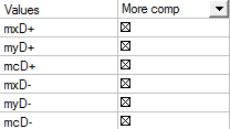
Plate XY |
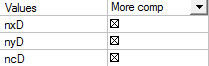
Wall XY |
General XYZ |
|
|
|
|
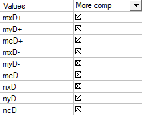
Description of the values above:
|
mxD+, mxD- |
Design bending moment in the X axis direction of the local coordinate system (LCS) for lower surface (-) or upper surface (+). |
|
myD+, myD+ |
Design bending moment in the Y axis direction of the local coordinate system (LCS) for lower surface (-) or upper surface (+). |
|
nxD+, nxD- |
Design normal force in the X axis direction of the local coordinate system (LCS) for lower surface (-) or upper surface (+). |
|
nyD+, nyD+ |
Design normal force in the Y axis direction of the local coordinate system (LCS) for lower surface (-) or upper surface (+). |
|
mcD+, mcD- |
Design bending moment in the concrete compression strut for lower surface (-) or upper surface (+) which must be covered by concrete. |
|
ncD-, ncD+ |
Design normal force in the concrete compression strut for lower surface (-) or upper surface (+) which must be covered by concrete. |
The upper and lower surface of 2D member is determined by the Z axis direction of the local coordinate system (LCS). The upper surface is in the positive direction of the Z axis and on the other hand the Lower surface is in negative direction of Z axis. The upper surface values are marked with + and the lower surface values are marked with -.
Comparison of design internal forces in Concrete Advanced and Results trees
The Design internal forces magnitudes in Concrete Advanced tree and Results tree have the same values only when the selected 2D member:
- has only two reinforcement directions defined and these are perpendicular to each other
- the first reinforcement direction angle is identical with the value of rotation defined in properties of Member 2D – Internal Forces in the Results tree.
|
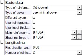
Member Data in Concrete Advanced tree |
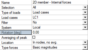
Member 2D - Internal Forces in Results tree |
|
|
|
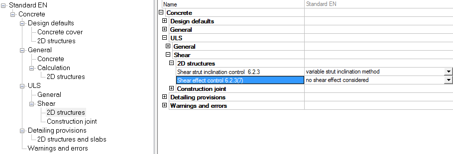
- influence of tension force is not considered for shear reinforcement,. That means that attribute Shear effect control 6.2.3(7) is set to no shear effect is considered possibility in the concrete setup dialog
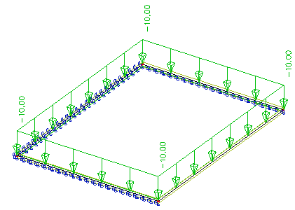
Comparison of the results in the Results and Concrete trees will be done for the type of the structure set to Plate XY. The structure is a simple 2D concrete member which dimensions are 6 x 8 meters and the thickness is 200 mm. It has defined concrete C25/30 and it is supported on three sides. It is subject to a constant surface load of 10 kN/m2. No member data are defined on this 2D member.
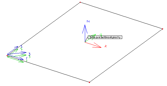
Two perpendicular reinforcement directions, identical with X and Y axes of LCS
First direction angle in Member data is set to 0 (zero) degrees and Rotation attribute in 2D Members – internal Forces properties in Results tree is 0 (zero) as well. The influence of tension force is not considered for shear reinforcement. That means that attribute Shear effect control 6.2.3(7) is set to no shear effect is considered possibility in the concrete setup dialog.
|
Reinforcement and LCS directions |
Member 2D - Internal Forces attributes |
|
|
|
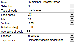
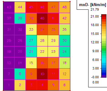
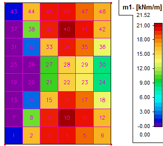
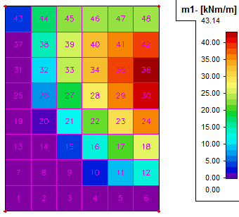
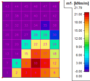
Graphical comparison of moment for lower surface for direction 1 (direction of X axis of LCS)
|
Results, moment mxD- |
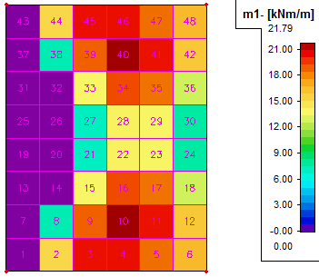
Concrete, moment m1- |
|
|
|
Numerical comparison of the moment for both surfaces and directions for elements 1-24 (half of the 2D member)
|
Moments |
Results tree |
Concrete tree |
|||||||||||
|
Case |
Elem. |
mxD- |
myD- |
mcD- |
mxD+ |
myD+ |
mcD+ |
m1- |
m2- |
mc- |
m1+ |
m2+ |
mc+ |
|
LC1 |
1 |
0 |
5,37 |
-15,73 |
17,04 |
8,78 |
-15,46 |
0 |
5,37 |
-15,73 |
17,04 |
8,78 |
-15,46 |
|
LC1 |
2 |
15,32 |
19,72 |
-34,61 |
19,29 |
14,89 |
-34,61 |
15,32 |
19,72 |
-34,61 |
19,29 |
14,89 |
-34,61 |
|
LC1 |
3 |
20,37 |
24,31 |
-37,97 |
17,6 |
13,66 |
-37,97 |
20,37 |
24,31 |
-37,97 |
17,6 |
13,66 |
-37,97 |
|
LC1 |
4 |
20,38 |
25,18 |
-35,29 |
14,91 |
10,11 |
-35,29 |
20,38 |
25,18 |
-35,29 |
14,91 |
10,11 |
-35,29 |
|
LC1 |
5 |
18,58 |
25,07 |
-31,73 |
13,16 |
6,67 |
-31,73 |
18,58 |
25,07 |
-31,73 |
13,16 |
6,67 |
-31,73 |
|
LC1 |
6 |
16,58 |
25,62 |
-30,36 |
13,78 |
4,74 |
-30,36 |
16,58 |
25,62 |
-30,36 |
13,78 |
4,74 |
-30,36 |
|
LC1 |
7 |
0 |
-2,47 |
-27,44 |
32,06 |
9,85 |
-11,99 |
0 |
0 |
0 |
32,06 |
9,85 |
-11,99 |
|
LC1 |
8 |
7,47 |
18,18 |
-27,91 |
20,45 |
9,74 |
-27,91 |
7,47 |
18,18 |
-27,91 |
20,45 |
9,74 |
-27,91 |
|
LC1 |
9 |
18,85 |
27,48 |
-31,53 |
12,68 |
4,05 |
-31,53 |
18,85 |
27,48 |
-31,53 |
12,68 |
4,05 |
-31,53 |
|
LC1 |
10 |
21,79 |
32,58 |
-29,65 |
5,42 |
0 |
-30,14 |
21,79 |
32,58 |
-29,65 |
5,42 |
0 |
-30,14 |
|
LC1 |
11 |
20,33 |
35,78 |
-26,79 |
1,07 |
0 |
-30,4 |
20,33 |
35,78 |
-26,79 |
1,07 |
0 |
-30,4 |
|
LC1 |
12 |
16,07 |
38,62 |
-25,51 |
2,98 |
0 |
-32,16 |
16,07 |
38,62 |
-25,51 |
2,98 |
0 |
-32,16 |
|
LC1 |
13 |
0 |
-5,77 |
-38,35 |
41,67 |
9,81 |
-7,36 |
0 |
0 |
0 |
41,67 |
9,81 |
-7,36 |
|
LC1 |
14 |
0 |
11,56 |
-17,93 |
19,42 |
4,57 |
-17,63 |
0 |
11,56 |
-17,93 |
19,42 |
4,57 |
-17,63 |
|
LC1 |
15 |
13,87 |
24,57 |
-20,49 |
3,7 |
0 |
-21,66 |
13,87 |
24,57 |
-20,49 |
3,7 |
0 |
-21,66 |
|
LC1 |
16 |
19,31 |
32,66 |
-19,57 |
-5,33 |
0 |
-27,06 |
19,31 |
32,66 |
-19,57 |
0 |
0 |
0 |
|
LC1 |
17 |
18,47 |
38,52 |
-17,79 |
-6,91 |
0 |
-32,3 |
18,47 |
38,52 |
-17,79 |
0 |
0 |
0 |
|
LC1 |
18 |
12,78 |
43,14 |
-16,85 |
-2,31 |
0 |
-36,76 |
12,78 |
43,14 |
-16,85 |
0 |
0 |
0 |
|
LC1 |
19 |
0 |
-7,29 |
-44,11 |
45,31 |
8,56 |
-2,47 |
0 |
0 |
0 |
45,31 |
8,56 |
-2,47 |
|
LC1 |
20 |
0 |
4,7 |
-13,69 |
15,23 |
0 |
-6,25 |
0 |
4,7 |
-13,69 |
15,23 |
0 |
-6,25 |
|
LC1 |
21 |
7,2 |
18,76 |
-7,07 |
-2,85 |
0 |
-16,04 |
7,2 |
18,76 |
-7,07 |
0 |
0 |
0 |
|
LC1 |
22 |
14,1 |
28,37 |
-6,82 |
-10,23 |
0 |
-25,43 |
14,1 |
28,37 |
-6,82 |
0 |
0 |
0 |
|
LC1 |
23 |
13,95 |
35,89 |
-6,22 |
-10,54 |
0 |
-33,08 |
13,95 |
35,89 |
-6,22 |
0 |
0 |
0 |
|
LC1 |
24 |
7,78 |
41,62 |
-5,87 |
-4,62 |
0 |
-38,9 |
7,78 |
41,62 |
-5,87 |
0 |
0 |
0 |
It is obvious from the table that design forces are identical in both trees.
Two perpendicular reinforcement directions, identical with X and Y axes of LCS, shear effect considered
The same settings as in the previous chapter will be used here with one exception. The influence of the tension force is considered for shear reinforcement. That means that attribute Shear effect control 6.2.3(7) is set to shear effect considered unconditionally possibility in the concrete setup dialog.
Graphical comparison of moment for lower surface for direction 1 (direction of X axis of LCS)
|
Results, moment mxD- |
Concrete, moment m1- |
|
|
|
Numerical comparison of moment for both surfaces and directions for elements 1-24 (half of the 2D member)
|
Moments |
Results tree |
Concrete tree |
|||||||||||
|
Case |
Elem. |
mxD- |
myD- |
mcD- |
mxD+ |
myD+ |
mcD+ |
m1- |
m2- |
mc- |
m1+ |
m2+ |
mc+ |
|
LC1 |
1 |
0 |
5,37 |
-15,73 |
17,04 |
8,78 |
-15,46 |
1,14 |
12,19 |
-19,1 |
16,11 |
10,66 |
-11,83 |
|
LC1 |
2 |
15,32 |
19,72 |
-34,61 |
19,29 |
14,89 |
-34,61 |
16,36 |
19,66 |
-34,49 |
20,44 |
14,96 |
-34,73 |
|
LC1 |
3 |
20,37 |
24,31 |
-37,97 |
17,6 |
13,66 |
-37,97 |
20,01 |
25,22 |
-36,8 |
18,42 |
15,74 |
-39,14 |
|
LC1 |
4 |
20,38 |
25,18 |
-35,29 |
14,91 |
10,11 |
-35,29 |
20,09 |
27,35 |
-34,63 |
15,29 |
12,94 |
-35,95 |
|
LC1 |
5 |
18,58 |
25,07 |
-31,73 |
13,16 |
6,67 |
-31,73 |
18,47 |
27,86 |
-31,52 |
13,27 |
9,68 |
-31,95 |
|
LC1 |
6 |
16,58 |
25,62 |
-30,36 |
13,78 |
4,74 |
-30,36 |
16,7 |
31,28 |
-30,59 |
13,66 |
10,15 |
-30,12 |
|
LC1 |
7 |
0 |
-2,47 |
-27,44 |
32,06 |
9,85 |
-11,99 |
0 |
1,36 |
-25,5 |
33,34 |
8,98 |
-6,64 |
|
LC1 |
8 |
7,47 |
18,18 |
-27,91 |
20,45 |
9,74 |
-27,91 |
10,84 |
18,74 |
-28,88 |
22,85 |
9,33 |
-26,95 |
|
LC1 |
9 |
18,85 |
27,48 |
-31,53 |
12,68 |
4,05 |
-31,53 |
19,83 |
27,09 |
-30,23 |
14,96 |
4,95 |
-32,82 |
|
LC1 |
10 |
21,79 |
32,58 |
-29,65 |
5,42 |
0 |
-30,14 |
21,52 |
32,98 |
-28,07 |
8,29 |
0 |
-31,29 |
|
LC1 |
11 |
20,33 |
35,78 |
-26,79 |
1,07 |
0 |
-30,4 |
20,08 |
37,19 |
-26,18 |
2,19 |
0 |
-29,74 |
|
LC1 |
12 |
16,07 |
38,62 |
-25,51 |
2,98 |
0 |
-32,16 |
16,42 |
42,86 |
-26,16 |
3,76 |
0 |
-28,99 |
|
LC1 |
13 |
0 |
-5,77 |
-38,35 |
41,67 |
9,81 |
-7,36 |
0 |
0 |
0 |
45,64 |
8,54 |
-3,65 |
|
LC1 |
14 |
0 |
11,56 |
-17,93 |
19,42 |
4,57 |
-17,63 |
2,78 |
13,57 |
-18,56 |
23,08 |
4,16 |
-16,69 |
|
LC1 |
15 |
13,87 |
24,57 |
-20,49 |
3,7 |
0 |
-21,66 |
16,19 |
24,35 |
-20 |
6,64 |
0 |
-22 |
|
LC1 |
16 |
19,31 |
32,66 |
-19,57 |
-5,33 |
0 |
-27,06 |
19,92 |
32,35 |
-18,31 |
0 |
0 |
0 |
|
LC1 |
17 |
18,47 |
38,52 |
-17,79 |
-6,91 |
0 |
-32,3 |
18,27 |
38,92 |
-16,98 |
0 |
0 |
0 |
|
LC1 |
18 |
12,78 |
43,14 |
-16,85 |
-2,31 |
0 |
-36,76 |
13,31 |
45,87 |
-17,74 |
0 |
0 |
0 |
|
LC1 |
19 |
0 |
-7,29 |
-44,11 |
45,31 |
8,56 |
-2,47 |
0 |
0 |
0 |
51,31 |
7,98 |
-1,19 |
|
LC1 |
20 |
0 |
4,7 |
-13,69 |
15,23 |
0 |
-6,25 |
0 |
5,24 |
-9,48 |
19,71 |
0 |
-5,98 |
|
LC1 |
21 |
7,2 |
18,76 |
-7,07 |
-2,85 |
0 |
-16,04 |
10,16 |
18,7 |
-6,95 |
0,18 |
0 |
-16,07 |
|
LC1 |
22 |
14,1 |
28,37 |
-6,82 |
-10,23 |
0 |
-25,43 |
15,52 |
28,19 |
-6,4 |
0 |
0 |
0 |
|
LC1 |
23 |
13,95 |
35,89 |
-6,22 |
-10,54 |
0 |
-33,08 |
14,18 |
35,77 |
-5,73 |
0 |
0 |
0 |
|
LC1 |
24 |
7,78 |
41,62 |
-5,87 |
-4,62 |
0 |
-38,9 |
8,49 |
42,69 |
-6,72 |
0 |
0 |
0 |
It is obvious from the table that the design forces are different in both trees. It is due to the fact that in Concrete tree the tension force from shear stress is considered. In this case it is necessary to make check of internal forces only in the Concrete tree.
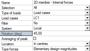
Two perpendicular reinforcement directions, rotated with 45 degrees according to the LCS
First direction angle in Member data is set to 45 degrees and Rotation attribute in 2D Members – internal Forces properties in Results tree is 45 degrees as well. The influence of the tension force is not considered for shear reinforcement. That means that attribute Shear effect control 6.2.3(7) is set to no shear effect is considered possibility in the concrete setup dialog.
|
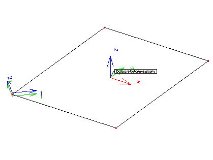
Reinforcement and LCS directions |
Member 2D - Internal Forces attributes |
|
|
|
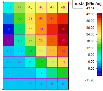
Graphical comparison of moment for lower surface for direction 1 (direction of X axis of LCS)
|
Results, moment mxD- |
Concrete, moment m1- |
|
|
|
Numerical comparison of moment for both surfaces and directions for elements 1-24 (half of the 2D member)
|
Moments |
Results tree |
Concrete tree |
|||||||||||
|
Case |
Elem. |
mxD- |
myD- |
mcD- |
mxD+ |
myD+ |
mcD+ |
m1- |
m2- |
mc- |
m1+ |
m2+ |
mc+ |
|
LC1 |
1 |
0 |
3,87 |
-14,23 |
17,04 |
1,58 |
-8,25 |
0 |
3,87 |
-14,23 |
17,04 |
1,58 |
-8,25 |
|
LC1 |
2 |
0 |
17,8 |
-17,37 |
17,37 |
0 |
-17,8 |
0 |
17,8 |
-17,37 |
17,37 |
0 |
-17,8 |
|
LC1 |
3 |
0 |
22,59 |
-15,88 |
15,8 |
0 |
-22,52 |
0 |
22,59 |
-15,88 |
15,8 |
0 |
-22,52 |
|
LC1 |
4 |
0 |
23,24 |
-12,97 |
12,76 |
0 |
-23,03 |
0 |
23,24 |
-12,97 |
12,76 |
0 |
-23,03 |
|
LC1 |
5 |
0 |
22,88 |
-10,97 |
10,39 |
0 |
-22,3 |
0 |
22,88 |
-10,97 |
10,39 |
0 |
-22,3 |
|
LC1 |
6 |
0 |
23,31 |
-11,46 |
10,23 |
0 |
-22,07 |
0 |
23,31 |
-11,46 |
10,23 |
0 |
-22,07 |
|
LC1 |
7 |
0 |
-3,08 |
-26,84 |
32,06 |
20,07 |
-22,21 |
0 |
0 |
0 |
32,06 |
20,07 |
-22,21 |
|
LC1 |
8 |
0 |
14,72 |
-16,99 |
17,33 |
0 |
-15,06 |
0 |
14,72 |
-16,99 |
17,33 |
0 |
-15,06 |
|
LC1 |
9 |
0 |
25,39 |
-10,6 |
9,17 |
0 |
-23,97 |
0 |
25,39 |
-10,6 |
9,17 |
0 |
-23,97 |
|
LC1 |
10 |
2,92 |
32,58 |
-10,79 |
3,54 |
0 |
-28,25 |
2,92 |
32,58 |
-10,79 |
3,54 |
0 |
-28,25 |
|
LC1 |
11 |
8,99 |
35,78 |
-15,45 |
0,86 |
0 |
-30,18 |
8,99 |
35,78 |
-15,45 |
0,86 |
0 |
-30,18 |
|
LC1 |
12 |
13,11 |
38,62 |
-22,55 |
2,82 |
0 |
-31,99 |
13,11 |
38,62 |
-22,55 |
2,82 |
0 |
-31,99 |
|
LC1 |
13 |
0 |
-8,52 |
-35,6 |
41,67 |
34,31 |
-31,86 |
0 |
0 |
0 |
41,67 |
34,31 |
-31,86 |
|
LC1 |
14 |
0 |
10,22 |
-16,59 |
19,42 |
1,8 |
-14,85 |
0 |
10,22 |
-16,59 |
19,42 |
1,8 |
-14,85 |
|
LC1 |
15 |
4,08 |
24,57 |
-10,7 |
2,76 |
0 |
-20,71 |
4,08 |
24,57 |
-10,7 |
2,76 |
0 |
-20,71 |
|
LC1 |
16 |
13,09 |
32,66 |
-13,36 |
-4,69 |
0 |
-27,7 |
13,09 |
32,66 |
-13,36 |
0 |
0 |
0 |
|
LC1 |
17 |
20,73 |
38,52 |
-20,05 |
-7,18 |
0 |
-32,03 |
20,73 |
38,52 |
-20,05 |
0 |
0 |
0 |
|
LC1 |
18 |
26,29 |
43,14 |
-30,36 |
-2,87 |
0 |
-36,2 |
26,29 |
43,14 |
-30,36 |
0 |
0 |
0 |
|
LC1 |
19 |
0 |
-11,93 |
-39,47 |
45,31 |
42,84 |
-36,75 |
0 |
0 |
0 |
45,31 |
42,84 |
-36,75 |
|
LC1 |
20 |
1,02 |
7,01 |
-17,01 |
15,99 |
10,01 |
-17,01 |
1,02 |
7,01 |
-17,01 |
15,99 |
10,01 |
-17,01 |
|
LC1 |
21 |
11,69 |
18,76 |
-11,55 |
-3,34 |
0 |
-15,55 |
11,69 |
18,76 |
-11,55 |
0 |
0 |
0 |
|
LC1 |
22 |
21,55 |
28,37 |
-14,27 |
-12,02 |
0 |
-23,63 |
21,55 |
28,37 |
-14,27 |
0 |
0 |
0 |
|
LC1 |
23 |
29,67 |
35,89 |
-21,95 |
-13,87 |
0 |
-29,75 |
29,67 |
35,89 |
-21,95 |
0 |
0 |
0 |
|
LC1 |
24 |
35,75 |
41,62 |
-33,84 |
-7,24 |
0 |
-36,29 |
35,75 |
41,62 |
-33,84 |
0 |
0 |
0 |
It is obvious from the table that design forces are identical in both trees. It is due to the fact that only two perpendicular reinforcement directions are defined and the first reinforcement direction angle is identical with the rotation angle defined in 2D Member – Internal Forces attributes, in Results tree. If different reinforcement direction angles were defined in 2D Member data for lower and upper surfaces, then the results in the Results tree would have to be recalculated separately for each surface.
Two non-perpendicular or three reinforcement directions
Three angles of 0, 45 and 90 degrees are defined in Member data. Rotation attribute in 2D Members – Internal Forces, in Results tree, has 0 (zero) value. The influence of the tension force is not considered for shear reinforcement. That means that attribute Shear effect control 6.2.3(7) is set to no shear effect is considered possibility in the concrete setup dialog
|
Reinforcement and LCS directions |
Member 2D - Internal Forces attributes |
|
|
|
Graphical comparison of moment for lower surface for direction 1 (direction of X axis of LCS)
|
Results, moment mxD- |
Concrete, moment m1- |
|
|
|
In this case the results will be different in both trees. Results in Result tree can’t be “fixed“ with LCS rotation or by adjusting Rotation attribute. General transformation would have to be used. In this case it is necessary to make the check of internal forces only in Concrete tree.
Determination of design internal forces in Results and Concrete tree
As it was mentioned before, different methods are used for determination of design internal forces in these two trees. For determination of design values in Results tree, the method described in literature [2] is used, while the method described in literature [3] is used for the determination of design values in Concrete tree. Demonstration of this determination will be presented on the same structure as was used in chapter 3.2.2.2.2.1. It will be done for element number 10 where the moment m1- (mxD-) has the largest value.
Determination of design internal forces in Results tree
|
Value |
Conditions and formulas |
Calculation |
|
mxD- |
(1) (2) (3) 0 if (4) |
mx =6,96 kNm < my = 17,75 kNm mx =6,96 kNm > -|mxy| = -14,83 kNm my =17.75 kNm > -|mxy| = -14,83 kNm
Condition (1) fulfilled, then:
mxD- =21,78 kNm |
|
myD- |
(1) (2) (3) (4) 0 if |
mx =6,96 kNm < my = 17,75 kNm mx =6,96 kNm > -|mxy| = -14,83 kNm my =17.75 kNm > -|mxy| = -14,83 kNm
Condition (1) fulfilled, then:
myD- =32,58 kNm |
|
mcD- |
(1) (2) (3) (4) |
mx =6,96 kNm < my = 17,75 kNm mx =6,96 kNm > -|mxy| = -14,83 kNm my =17.75 kNm > -|mxy| = -14,83 kNm
Condition (1) fulfilled, then:
mcD- =-29,66 kNm |
|
mxD+ |
(1) (2) (3) (4) 0 if |
mx = 6,96 kNm < my = 17,75 kNm mx = 6,96 kNm < |mxy| = 14,83 kNm my = 17.75 kNm > |mxy| = 14,83 kNm
Condition (3) fulfilled, then:
|
|
myD+ |
(1) (2) (3) 0 if (4) |
mx =6,96 kNm < my = 17,75 kNm mx =6,96 kNm > -|mxy| = -14,83 kNm my =17.75 kNm > -|mxy| = -14,83 kNm
Condition (3) fulfilled, then: myD+ =0 kNm |
|
mcD+ |
(1) (2) (3) (4) |
mx =6,96 kNm < my = 17,75 kNm mx =6,96 kNm > -|mxy| = -14,83 kNm my =17.75 kNm > -|mxy| = -14,83 kNm
Condition (3) fulfilled, then:
|
 if
if  and
and 
 and
and 

 if
if  and
and 

 if
if  if
if 


 if
if  if
if  if
if 
 if
if 

 if
if 

 mxD+ = 5,43 kNm
 if
if
 if
if  if
if  if
if  if
if  mcD+ = 30,14 kNm
Determination of design internal forces in Concrete tree
According to this method the basic internal forces and their directions must be determined first. In SCIA Engineer these magnitudes are presented in Results in 2D Members – Inner forces item, if the type of the value is set to Basic magnitudes possibility.
|
Value |
Formulas |
Calculation |
|
z |
Determination of effective height and lever arm. z = 0,9d |
dlo = dup= 200-45 = 155 mm z = 0,9·d = 0,9·155= = 139,5 mm |
|
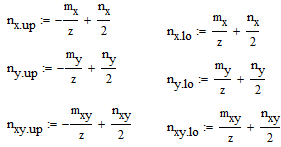
nx,lo(up) ny,lo(up) nxy,lo(up)
|
Determination of normal forces for lower and upper surface in LCS
|
nx.up = -49,89 kN ny.up = -127,24 kN nxy.up = 106,38 kN nx.lo = 49,89 kN ny.lo = 127,24 kN nxy.lo = -106,38 kN |
|
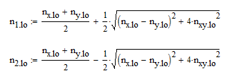
n1,lo(up) n2,lo(up)
|
Determination of principal forces for lower surface
|
n1,lo = 201,7 kN n2,lo = -24,55 kN n1,up = 24,55 kN n2,up = -201,37 kN |
|
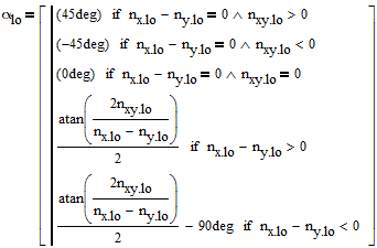
α,lo(up)
|
Determination of principal forces directions
|
αlo = -55 deg αup = 35 deg |
|
αlc,lo(up) |
Determination of compression strut angle in concrete. The angle of compression strut is optimised to allow for the smallest force in compression strut. |
αlc,lo = 45 deg αlc,up = 129 deg |
|
αj,lo(up) |
Determination of angle between the reinforcement direction and the direction of principal forces. α1,lo = αr1,lo - αlo α2,lo = αr2,lo - αlo α3,lo = αrc,lo - αlo
|
α1,lo = 0 - (-55) = 55 deg α2,lo = 90 - (-55) = 145 deg α3,lo = 45 - (-55) = 100 deg α1,up = 0 - 35 = -35 deg α2,up = 90 - 35 = 55 deg α3,up = 129 - 35 = 94 deg
|
|
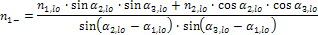
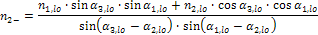
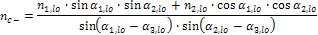
nj,-(+) |
Determination of design forces in reinforcement’s direction, i.e. in direction of compression strut. Baumann transformation formula, adjusted for two reinforcement directions, is used.
|
n1- =156,2 kN n2- =233,5 kN nc- =-212,6 kN n1+ =39 kN n2+ =-0,09 kN nc+ =-216,03 kN |
|
mj,-(+) |
While type of the structure is set to Plate, design forces will be transformed into moments by formula
m =n·z
|
m1- = 21,79 kNm m2- = 32,58 kNm mc- =-29,66 kN m1+ = 5,44 kNm m2+ = -0,014 kNm mc+ =-30,14 kN
|
Formulas in the tables are usually named for lower surface only, but the same formulas with changed indexes stands good for the upper surface.
Determination of design internal forces for General XYZ structure
Normal forces in reinforcement and compression strut directions for both surfaces are presented when structure type is set to General XYZ possibility. Sometimes, for further checks, it is necessary to replace these normal forces with the effect of moment and normal force which are located in the centre of gravity of the member. If reinforcement directions for both surfaces are identical, then it is possible to determine these effect using the formulas bellow.
mj =(dj- – 0,5h)·nj- + (0,5h - dj+)·nj+
nj =nj- + nj+
Wherej stands for reinforcement direction
dj-(+) stands for effective height in j reinforcement direction for lower (-) and upper (+) surface
nj-(+) stands for the values of normal forces in reinforcement direction for lower (-) and upper (+) surface presented in numerical values
If reinforcement directions for both surfaces are not identical, then the determination is more difficult, because it is necessary to calculate normal forces for upper surface (nvj+) and lower surface (nvj-) separately. Then the calculation uses the formulas bellow.
mj- =(dj- – 0,5h)·nj- + (0,5h - dj+)·nvj+(moment in lower reinforcement direction)
mj+ =(0,5h - dj+)·nj+ + (dj- – 0,5h)·nvj-(moment in upper reinforcement direction)
nj- =nj- + nvj+(force in lower reinforcement direction)
nj+ =nj+ + nvj-(force in upper reinforcement direction)
Recalculation will be done for identical reinforcement directions for both upper and lower surface and structure from chapter 3.2.2.2.2.1. Only Structure type of this project will be changed from Plate XY to General XYZ. After the change, these design magnitudes will be displayed in Concrete tree.
Recalculation of normal forces for both surfaces to forces which take place in the centre of the gravity will be done for mesh element number 10.
|
Value |
Formulas |
Calculation |
|
dj |
Determination of effective height. dj = h- cj – 0,5×dsj |
d1= d1- = d1+= 200-35-0,5×10 = 160 mm d2= d2- = d2+= 200-45-0,5×10 = 150 mm |
|
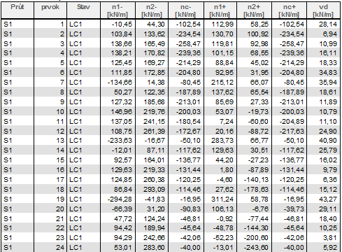
m1 n1 |
Determination of normal forces in reinforcement direction 1 (0 degree). m1 =(d1 – 0,5h)·n1- +(0,5h- d1)·n1+ n1 =n1+ + n1-
|
n1+= 146,5 kN/m n1-= 53,1 kN/m m1 = 5,6 kNm/m n1 = 199,6 kN/m |
|
m2 n2 |
Determination of normal forces in reinforcement direction 2 (90 degree). m2 =(d2 – 0,5h)·n2- +(0,5h- d2)·n2+ n2 =n2+ + n2-
|
n2-= 219,8 kN/m n2+= -19,73 kN/m m2 = 11,97 kNm/m n2 = 200,1 kN/m |
Determination of inner forces with influence of shear force
As it was mentioned in previous chapters, values of design magnitudes in Concrete tree depend on whether the influence of tension force from shear is taken into consideration. This influence may be changed in Concrete setup dialog under Concrete > ULS > Shear > 2D Structures. If this influence is taken into consideration, then resultant of tension force from shear (value DFtdj) is incremented to the resultant of principal forces. More on this issue can be found in chapter 3.2.2.1.
Again, calculation will be done for structure from chapter 3.2.2.2.2.1 for mesh element number 10, where the design moment m1- (mDx-) reaches its maximum.
|
Value |
Formulas |
Calculation |
|
vd |
Determination of resultant shear force.
|
vd = 10,79 kN |
|
β |
Determination of resultant shear force direction.
|
β = 56,53 deg |
|
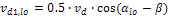
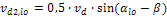
vdj,lo(up) |
Recalculation of resultant shear force to the principal forces directions, where 50% will be added to upper and 50% to lower surface.
|
vd1,lo = -1.98 kN vd2,lo = -5 kN vd1,up = 5 kN vd2,up = -1,98 kN |
|
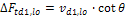
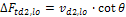
ΔFtdj,lo(up) |
Determination of tension force increment from shear.
|
DFtd1,lo= -4,95 kN DFtd2,lo= 12,55 kN DFtd1,up= 12,55 kN DFtd2,up= -4,95 kN
|
|
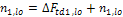
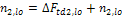
n1,lo(up) n2,lo(up)
|
Principal inner forces with shear increment
For recalculation of principal force is compression strut angle determined and design values calculated. |
n1,lo = 199,7 kN n2,lo = -12 kN n1,up = 37,1 kN n2,up = -206,32 kN |


During the calculation of tension force from shear according to the EN 1992-1-1, chapter 6.2.3 (7) condition MEd/z + ΔFtd ≤ MEd,max/z is being checked.
Resultant shear force is presented directly in Design magnitudes in Concrete tree as vd and also in Results tree in 2D Members – Internal forces, for attribute type forces set to Principal magnitudes possibility. It is named as qmax-b.
Resultant shear force angle is presented in Results tree under 2D Members – Internal forces, for attribute type forces set to Principal magnitudes possibility. It is named as beta. In Concrete tree it can be found under Member design ULS, for attribute output set to Advanced or Detailed, for Asw value.
Shear strut inclination (angle θ) is displayed in Concrete Advanced tree and it can be found under Member design ULS, for attribute output set to Advanced or Detailed, for Asw value.