Calculation procedure
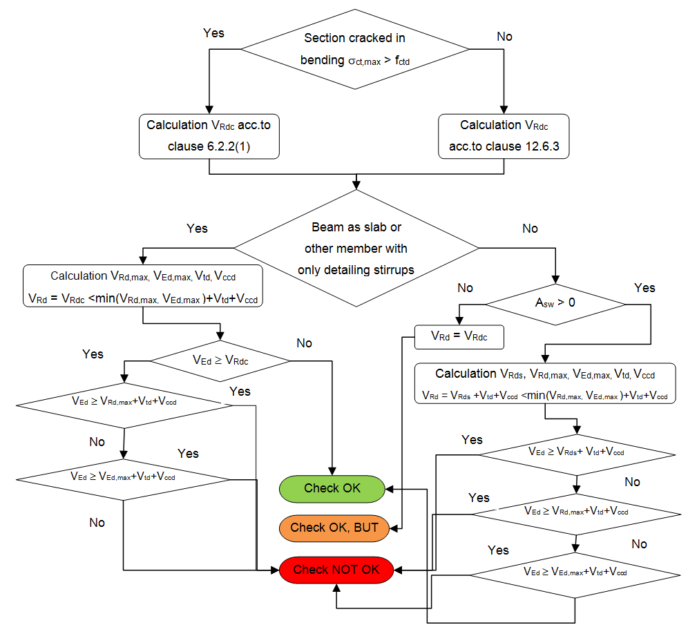
As mentioned above, it exists general concept of "strut-and-tie" model for the prediction of shear effects in concrete. In this model, the top compression and bottom tensile members represent the compressive concrete and tensile reinforcement, respectively. The horizontal members are connected by the compressive virtual struts and reinforcement tensile ties. The axial forces in tensile ties should be transmitted by the shear reinforcement. Consequently, the maximal force in concrete struts (VRd,max) and shear force retained by the shear resistance (VRd,s) have to be compared with acting shear force (VEd). The procedure for check can be represented by diagram below:
The formulas which are used for the calculation of each component of this model are the following.
Generally, there are two possibilities for calculation of shear capacity of concrete dependently on existence of cracks in bending:
Shear concrete capacity in region cracked in bending - formula 6.2.a,b in EN 1992-1-1
VRd,c = [CRd,c ∙ k ∙ (100 ∙ ρl ∙ fck)1/3 + k1 ∙ σcp] ∙ bw ∙ d
VRd,c,min = (νmin + k1 ∙ σcp) ∙ bw ∙ d
Shear concrete capacity in region uncracked in bending – clause 12.6.3(3) in EN 1992-1-1
VRd,c = fcvd ∙ Acc / k12.6.3
Additionally, there is calculated maximal shear force (VEd,max)) without reduction by β for member where load is applied in the upper side of the member (see formula 6.5 in EN 1992-1-1).
VEd,max = 0,5 ∙ bw1 ∙ d ∙ ν ∙ fcd
Maximal capacity of concrete compressive strut (VRd,max) is determined according to formula 6.9 in EN 1992-1-1, because as has been mentioned before, the angle of stirrups (θ) is always perpendicular to member axis.
VRd,max = (αcw ∙ bw1 ∙ z ∙ ν1 ∙fcd) / (cot θ + tan θ)
Design value of shear force sustained by shear reinforcement (VRd,s) is calculated according to formula 6.13 in EN 1992-1-1
VRd,s = Asw / s ∙ z ∙ fywd ∙ (cot θ + cot α) ∙ sin α
Asw for formula 6.13 is limited to Asw,max according clause 6.2.2(3)
Asw,max = αcw ∙ ν1 ∙ bw ∙ fcd ∙ sl / (fywd ∙ (1 + cotg(θ)2) ∙ sin α)
where
Final design value of shear force (VRd) carried by member is calculated based on the following formulas depending on type of member and area of shear reinforcement.
VRd = VRd,c ≤ min(VRd,max, VEd,max) + Vtd + Vccd
- for other cases
VRd = VRd,s + Vtd + Vccd ≤ min(VRd,max, VEd,max) + Vtd + Vccd
where
| VEd |
resultant of shear force VEd = √(VEd,y2 + VEd,z2) |
| VEd,y(z) | shear force in direction of y(z) axis of LCS |
| VRd,c | the design shear resistance of the member without shear reinforcement |
| σct,max | maximal tensile strength in uncracked cross-section |
| VRd,c,min | the minimal value of design shear resistance of the member without shear reinforcement |
| CRd,c | coefficient for calculation VRd,c loaded from Manager for National annexes |
| k |
coefficient of effective height of cross-section k = 1 + √(200 / d) ≤ 2 |
| ρl |
ratio of tensile reinforcement ρl = Asl / (bw ∙d) ≤ 0,02 |
| fck | characteristic compressive cylinder strength of concrete |
| k1 | coefficient for calculation VRd,c loaded from Manager for National annexes |
| σcp |
stress caused by axial force (NEd > 0 for compression) σcp = NEd / Ac ≤ 0,2 ∙ fcd |
| bw | the smallest width of the cross-section in tensile area of cross-section perpendicular to direction of resultant shear force, see "Width of cross-section for shear check" |
| d | effective depth of cross-section recalculated to direction of shear forces resultant, see "Effective depth of cross-section for shear check" |
| Asl | tensile area of reinforcement |
| NEd | the axial force in the cross-section due to loading or prestressing. |
| Ac | the area of concrete cross section |
| fcd | design value of concrete compressive strength |
| νmin | Coefficient of minimum value of shear resistance of the member without shear reinforcement loaded from Manager for National annexes,see equation 6.3N in EN 1992-1-1 |
| fcvd |
the concrete design strength in shear and compression, see equations 12.5 and 12.6 in EN 1992-1-1 if σccp ≤ σc,lim: fcvd = √(fctd2 + σccp ∙ fctd) if σccp > σc,lim: fcvd = √(fctd2 + σccp ∙ fctd - ((σccp - σc,lim) / 2)2) |
| fctd | design axial tensile strength of concrete |
| σccp |
normal (axial)stress of uncracked cross-section σccp = NEd / Acc |
| σc,lim | limit value of stress caused by axial force, see equations 12.7 in EN 1992-1-1 σc,lim = fcd - 2 ∙ √(fctd ∙ (fctd + fcd)) |
| Acc | compressed concrete area for uncracked cross-section |
| VEd,max | maximum value of shear force resultant calculated without reduction by coefficient β, see clause 6.2.2(6) in EN 1992-1-1 |
| bw1 | minimum width of cross-section between tension and compression chord perpendicular to direction of shear force, see "Width of cross-section for shear check" |
| ν | strength reduction factor for concrete cracked in shear loaded from Manager for National annexes, see equation 6.6N in EN 1992-1-1 |
| VRd,max | the design value of the maximum shear force which can be sustained by the member, limited by crushing of the compression struts |
| αcw | coefficient taking into account state of the stress in the compression chord, see note 3 in clause 6.2.3(3) in EN 1992-1-1. The value 1 is always taken into account for non -prestressed structures |
| z | inner lever arm of cross-section recalculated to direction of shear forces resultant, see "Inner lever arm for shear check" |
| ν1 |
strength reduction factor for concrete cracked in shear loaded from Manager for National annexes, see note 1 and 2 in clause 6.2.3(3) in EN 1992-1-1. if σswd > 0,8 ∙ fywk : ν1 = ν if σswd ≤ 0,8 ∙ fywk and fck ≤ 60 MPa: ν1 = 0,6 if σswd ≤ 0,8 ∙ fywk and fck > 60 MPa: ν1 = 0,9 - fck / 200 > 0,5 |
| θ | Angle between concrete compression strut and beam axis perpendicular to the shear force, see "Angle between concrete compression strut and beam axis" |
| σswd |
is design stress of the shear reinforcement σswd = VEd ∙ s / (z ∙ (cot θ + cot α) ∙ sin α) |
| VRd,s | design value of the shear force which can be sustained by the yielding shear reinforcement. |
| Asw | the cross-sectional area of the shear reinforcement calculated as average area from all stirrups within calculated interval, see "Calculation of average characteristics of shear reinforcement" |
| s | the spacing of the stirrups calculated as average area from all stirrups within calculated interval, see "Calculation of average characteristics of shear reinforcement" |
| fywd |
the design yield strength of the shear reinforcement. fywd = 0,8 ∙ fywk and σswd ≤ 0,8 ∙ fywk |
| α | angle of shear reinforcement . The angle of stirrups is always perpendicular (90 °) to member axis in SCIA Engineer |
| fywk | characteristic yield strength of the shear reinforcement |
| Vtd | the design value of the shear component of the force in the tensile reinforcement, in the case of an inclined tensile chord |
| Vccd | the design value of the shear component of the force in the compression area, in the case of an inclined compression chord |
For member with inclined chords the additional forces haves to be taken into account for shear check according to clause 6.2.1(1). The calculation is prepared for taking into account also inclined chords. Nevertheless the calculation itself is not implemented yet. The partial components are explained in the following figure.
