Shear check
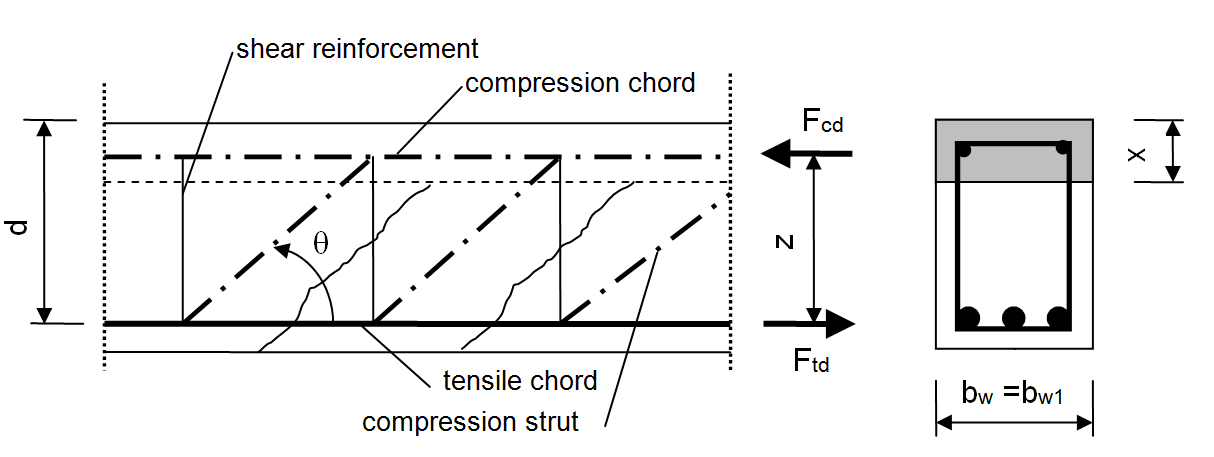
The shear check is commonly based on the theory of the concrete truss-model. In this theory a virtual truss-model is imagined in a concrete beam. This truss-model has a set of vertical (or slightly diagonal), horizontal and diagonal members. The vertical bars are considered to be the stirrups; the horizontal bars are the main reinforcement and the diagonal bars are the concrete struts. The check of biaxial shear is calculated according to preconditions in clause 6.2 in EN 1992-1-1.
There are the following assumptions:
- The shear forces in both direction is taken into account and shear check is done for resultant of shear force
- The parameters of plane of equilibrium (value, d, z and h) are recalculated to direction of resultant shear force
- The design shear resistance of the member without shear reinforcement (VRd,c) is calculated according to clause 6.2.2(1) in EN 1992-1-1, if section is cracked in flexure, otherwise clause 12.6.3 in EN 1992-1-1 is used
- Design value of maximum shear force will be calculated according to clause 6.2.2(6) (VEd,max) and 6.2.3 (3,4) (VRd,max) in EN 1992-1-1
- Design value of shear resistance is calculated according to 6.2.3 (3,4) (VRd,s) in EN 1992-1-1
- The number of shear link can be calculated automatically or defined by user (in properties of stirrup zone), see "Calculation number of stirrup link (number of cuts)"
- The angle of compression strut can be calculated automatically or defined by user, see "Angle between concrete compression strut and beam axis"
- The angle of stirrups for check is always perpendicular to member axis.
With the following limitations:
- Inclined compression chord or inclined tensile chord are not taken into account
- The width of cross-section for shear checks (value bw and bw1) are calculated automatically. There is no possibility to define user value in SCIA Engineer
- Free bars reinforcement is not taken into account
- The area of longitudinal reinforcement is not subtracted from concrete area