Theory
The calculation procedure can be described in the following steps:
1) Calculation of uncracked cross-section
The cross-section characteristics for uncracked cross-section (using the linear stress-strain diagram with a tensile branch for concrete and reinforcement) are calculated. This state is signed with bottom index I
.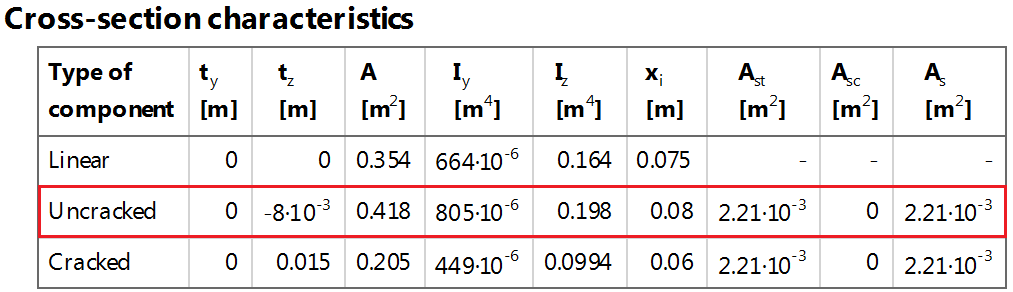
The values in table are the following:
ty - distance from centre of gravity of particular cross-section type to centre of gravity of concrete cross-section in (y) direction
tz - distance from centre of gravity of particular cross-section type to centre of gravity of concrete cross-section in (z) direction
A - area of particular cross-section type
Iy - moment of inertia for particular cross-section type around (y) direction
Iz - moment of inertia for particular cross-section type around (z) direction
x - depth of compressive zone for particular cross-section type
Ast - area of tensile reinforcement for particular cross-section type
Asc - area of compressive reinforcement for particular cross-section type
A - area of total reinforcement for particular cross-section type
2) Calculation of tensile concrete strength used for crack appearance
Stiffness and deflections are dependent significantly on the effective concrete strength which governs the cracking moment. Value of strength for determination if crack appears or not, see chapter "Value of strength for calculation of cracking forces"The resultant value is effective tensile concrete strength σcr which can be fctm or fctm,fl. Additionally, there is possibility to set tensile strength or 0 MPa.
3) Verification of crack appearance
At first crack appearance is verified for characteristic load combination in accordance to chapter 7.1(2) - maximal tensile stress in concrete fibre is compared with effective concrete tensile strength fct,eff. The calculation of maximal tensile stress in concrete fibre is performed on cross-section with SLS linear diagram of concrete with tensile branch and the reinforcement is taken into account with linear diagram. As a conclusion, two cases can appear:
1) σct ≤ σcr - no crack appears; the cross-section is considered as uncracked and SLS linear diagram with tension is used for another steps of the calculation.
2) σct > σcr - crack appears; the cross-section is considered as cracked; the cross-section is recalculated using SLS linear diagram without tension.
where
| σct | normal concrete stress on un-cracked section at the most tensioned fiber of concrete cross-section |
| σcr | is value of strength for determination if crack width will be calculated or not, see chapter "Value of strength for calculation of cracking forces" |
When the cracks appear then the following steps are done
4) Calculation of cracking internal forces
The cracking internal forces are calculated based on the uncracked CSS characteristics and tensile concrete strength. Afterwards, these cracking forces are used for calculation of stress in reinforcement (σsr).
5) Calculation of distribution coefficient
Beforehand the distribution coefficient, calculated from the reinforcement stress for acting load (σs) and for cracking load (σsr), has to be known. There is coefficient β which is determined according to duration of the load:
β = 1,0 - for short-term load
β = 0,5 - for long-term load (based on using Use effective modulus of concrete = true)
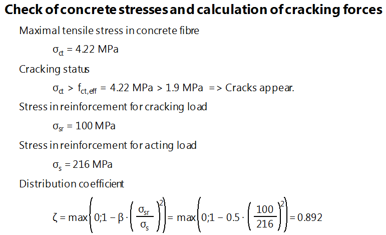
The distribution coefficient (in fact coefficient of tension stiffening) is calculated based on the type of load (β) and also on the ratio of reinforcement stress for cracking and acting load
ξ = 1 - β ∙ (σsr / σs)2
6) Calculation of fully cracked cross-section
The cross-section characteristic for full cracked cross-section (using linear stress-strain diagram without tensile branch for concrete and reinforcement) are calculated. This state is signed with bottom index II.
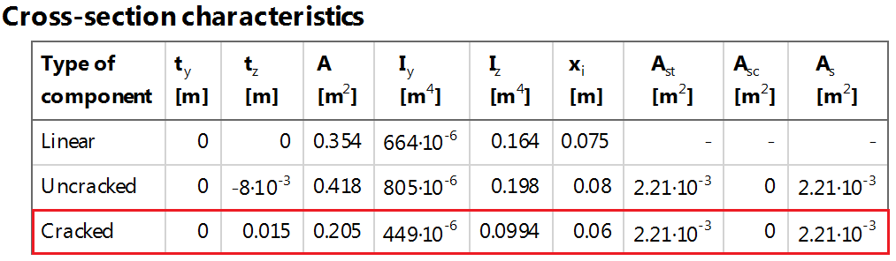
Explanation is mentioned above.
7) calculation of resultant values of stiffnesses and curvatures
When the steps above are calculated then resultant values of stiffnesses can be calculated using interpolation formula respecting uncracked state (I) and fully cracked state (II).
Calculation of the resultant bending stiffness,
EIy = 1 / [ξ / EIy,II + (1 - ξ) / EIy,I]
axial stiffness,
EA = 1 / [ξ / EAII + (1 - ξ) / EAI]
and curvatures.
1 / ry = ξ ∙ 1 / ry,II + (1 - ξ) ∙ 1 / ry,I
Output values
There are presented the following output values:
- EA - axial stiffness of the cross-section
- EIy - bending stiffness around (y) axis of the cross-section
- EIz - bending stiffness around (z) axis of the cross-section