Design Defaults
Design defaults
Reinforcement
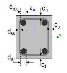
Beam/Rib
Longitudinal
Use a template of provided reinforcement
| Description |
Information about if the template of provided reinforcement is used or not |
| Default | Checkbox - ON |
|
Code |
- |
| Level | Standard |
|
Figure |
- |
| Member | Beam / Rib |
Upper
Diameter of upper reinforcement
| Description |
Information about diameter of upper of reinforcement |
| Default | Edit box; default ds,u = 16 mm |
|
Code |
- |
| Level | Standard |
|
Figure |
|
| Member | Beam / Rib |
Type of cover of upper reinforcement
| Description |
Information about type of cover of upper reinforcement |
| Default | Combo box; Auto / User; default = Auto |
|
Code |
4.4.1 |
| Level | Standard |
|
Figure |
|
| Member | Beam / Rib |
User defined concrete cover of upper reinforcement
| Description |
Possibility to define concrete cover of upper reinforcement; this item is visible only if the item above is set to User |
| Default | Edit box; cu = 30 mm |
|
Code |
4.4.1 |
| Level | Standard |
|
Figure |
|
| Member | Beam / Rib |
Lower
Diameter of lower reinforcement
| Description |
Information about diameter of lower of reinforcement |
| Default | Edit box; default ds,l = 16 mm |
|
Code |
- |
| Level | Standard |
|
Figure |
|
| Member | Beam / Rib |
Type of cover of lower reinforcement
| Description |
Information about type of cover of lower reinforcement |
| Default | Combo box; Auto / User; default = Auto |
|
Code |
4.4.1 |
| Level | Standard |
|
Figure |
|
| Member | Beam / Rib |
User defined concrete cover of lower reinforcement
| Description |
Possibility to define concrete cover of lower reinforcement; this item is visible only if the item above is set to User |
| Default | Edit box; cl = 30 mm |
|
Code |
4.4.1 |
| Level | Standard |
|
Figure |
|
| Member | Beam / Rib |
Side
Type of cover of side reinforcement
| Description |
Information about type of cover of side reinforcement |
| Default | Combo box; Auto / User; default = Auto |
|
Code |
4.4.1 |
| Level | Standard |
|
Figure |
|
| Member | Beam / Rib |
User defined concrete cover of side reinforcement
| Description |
Possibility to define concrete cover of side reinforcement; this item is visible only if the item above is set to User |
| Default | Edit box; cs = 30 mm |
|
Code |
4.4.1 |
| Level | Standard |
|
Figure |
|
| Member | Beam / Rib |
Stirrups
Diameter of stirrups
| Description |
Information about diameter of stirrups |
| Default | Edit box; dss = 8 mm |
|
Code |
- |
| Level | Standard |
|
Figure |
|
| Member | Beam / Rib |
Number of cuts
| Description |
Information about number of cuts for shear reinforcement |
| Default | Edit box; ns = 2 |
|
Code |
- |
| Level | Standard |
|
Figure |
|
| Member | Beam / Rib |
Angle
| Description |
Angle between shear reinforcement and the beam axis perpendicular to the shear force |
| Default | Edit box; α = 90 ° |
|
Code |
- |
| Level | Standard |
|
Figure |
- |
| Member | Beam / Rib |
Beam slab
Longitudinal
Upper
Diameter of upper reinforcement
| Description |
Information about diameter of upper of reinforcement |
| Default | Edit box; default ds,u = 16 mm |
|
Code |
- |
| Level | Standard |
|
Figure |
|
| Member | Beam slab |
Type of cover of upper reinforcement
| Description |
Information about type of cover of upper reinforcement |
| Default | Combo box; Auto / User; default = Auto |
|
Code |
4.4.1 |
| Level | Standard |
|
Figure |
|
| Member | Beam slab |
User defined concrete cover of upper reinforcement
| Description |
Possibility to define concrete cover of upper reinforcement; this item is visible only if the item above is set to User |
| Default | Edit box; cu = 30 mm |
|
Code |
4.4.1 |
| Level | Standard |
|
Figure |
|
| Member | Beam slab |
Lower
Diameter of lower reinforcement
| Description |
Information about diameter of lower of reinforcement |
| Default | Edit box; default ds,l = 16 mm |
|
Code |
- |
| Level | Standard |
|
Figure |
|
| Member | Beam slab |
Type of cover of lower reinforcement
| Description |
Information about type of cover of lower reinforcement |
| Default | Combo box; Auto / User; default = Auto |
|
Code |
4.4.1 |
| Level | Standard |
|
Figure |
|
| Member | Beam slab |
User defined concrete cover of lower reinforcement
| Description |
Possibility to define concrete cover of lower reinforcement; this item is visible only if the item above is set to User |
| Default | Edit box; cl = 30 mm |
|
Code |
4.4.1 |
| Level | Standard |
|
Figure |
|
| Member | Beam slab |
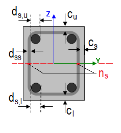
Column
Longitudinal
Main
Diameter of main reinforcement
| Description |
Information about diameter of main of reinforcement |
| Default | Edit box; default ds,m = 16 mm |
|
Code |
- |
| Level | Standard |
|
Figure |
|
| Member | Column |
Type of cover of main reinforcement
| Description |
Information about type of cover of main reinforcement |
| Default | Combo box; Auto / User; default = Auto |
|
Code |
4.4.1 |
| Level | Standard |
|
Figure |
|
| Member | Column |
User defined concrete cover of main reinforcement
| Description |
Possibility to define concrete cover of main reinforcement; this item is visible only if the item above is set to User |
| Default | Edit box; cm = 30 mm |
|
Code |
4.4.1 |
| Level | Standard |
|
Figure |
|
| Member | Column |
Stirrups
Diameter of stirrups
| Description |
Information about diameter of stirrups |
| Default | Edit box; dss = 8 mm |
|
Code |
- |
| Level | Standard |
|
Figure |
|
| Member | Column |
Number of cuts
| Description |
Information about number of cuts for shear reinforcement |
| Default | Edit box; ns = 2 |
|
Code |
- |
| Level | Standard |
|
Figure |
|
| Member | Column |
Angle
| Description |
Angle between shear reinforcement and the beam axis perpendicular to the shear force |
| Default | Edit box; α = 90 ° |
|
Code |
- |
| Level | Standard |
|
Figure |
- |
| Member | Column |
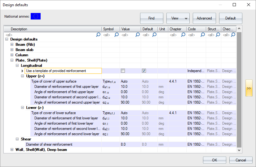
Plate, Shell (Plate)
The concrete settings for 2D members is different than 1D member, but the idea of usage of provided reinforcement library for design defaults is the same.
Longitudinal
Displaying of items in Design defaults for Plate and Shell (Plate) is dependent on setting Use a template of provided reinforcement, see above.
Use a template of provided reinforcement - True
When the provided reinforcement library is used then diameters for design are defined in design defaults directly.

Values of cover and angles are the same as in case of Use a provided reinforcement library is False. Diameter are linked via Provided reinforcement library
| Description |
Link to provided library based for Plate |
| Default | Link to library; default is the first value from the library |
|
Code |
- |
| Level | Standard |
|
Figure |
- |
| Member | Plate, Shell(Plate) |
Use a template of provided reinforcement - False
When the provided reinforcement library is not used then diameters for design are defined in design defaults directly.
Then there is definition of items based on surfaces - Upper (z+) / Lower (z-).
Upper (z+)
Type of cover of first layer of upper reinforcement
| Description |
Selection of type of cover for first layer of upper reinforcement - Auto / User |
| Default | Combo box; Typec1,u = Auto |
|
Code |
4.4.1 |
| Level | Standard |
|
Figure |
- |
| Member | Plate, Shell(Plate) |
User defined cover for upper reinforcement
| Description |
User defined value of cover for first layer of upper reinforcement. |
| Default | Edit box; cuser1,u = 30 mm; this item is visible only in case of Type of cover of upper reinforcement is User. |
|
Code |
4.4.1 |
| Level | Standard |
|
Figure |
- |
| Member | Plate, Shell(Plate) |
Diameter of first upper reinforcement layer
| Description |
Defined diameter of first upper reinforcement layer used during design procedure |
| Default | Edit box; ds1.u = 10 mm; this item is visible only if check box Use a template of provided reinforcement is set False. |
|
Code |
- |
| Level | Standard |
|
Figure |
|
| Member | Plate, Shell(Plate) |
Angle of first upper reinforcement layer
| Description |
Defined angle of first upper reinforcement layer used during design procedure from x axis of LCS 2D mesh element |
| Default | Edit box; α1.u = 0° |
|
Code |
- |
| Level | Standard |
|
Figure |
|
| Member | Plate, Shell(Plate) |
Diameter of second upper reinforcement layer
| Description |
Defined diameter of second upper reinforcement layer used during design procedure |
| Default | Edit box; ds2.u = 10 mm; this item is visible only if check box Use a template of provided reinforcement is set False. |
|
Code |
- |
| Level | Standard |
|
Figure |

|
| Member | Plate, Shell(Plate) |
Angle of first second reinforcement layer
| Description |
Defined angle of first second reinforcement layer used during design procedure from x axis of LCS 2D mesh element |
| Default | Edit box; α2.u = 90° |
|
Code |
- |
| Level | Standard |
|
Figure |
|
| Member | Plate, Shell(Plate) |
Minimal difference between angles of reinforcement layers is 15 °
Lower (z-)
Type of cover of first layer of lower reinforcement
| Description |
Selection of type of cover for first lower of lower reinforcement - Auto / User |
| Default | Combo box; Typec1,l = Auto |
|
Code |
4.4.1 |
| Level | Standard |
|
Figure |
- |
| Member | Plate, Shell(Plate) |
User defined cover for lower reinforcement
| Description |
User defined value of cover for first layer of lower reinforcement. |
| Default | Edit box; cuser1,l = 30 mm; this item is visible only in case of Type of cover of lower reinforcement is User. |
|
Code |
4.4.1 |
| Level | Standard |
|
Figure |
- |
| Member | Plate, Shell(Plate) |
Diameter of first lower reinforcement layer
| Description |
Defined diameter of first lower reinforcement layer used during design procedure |
| Default | Edit box; ds1.l = 10 mm; this item is visible only if check box Use a template of provided reinforcement is set False. |
|
Code |
- |
| Level | Standard |
|
Figure |
|
| Member | Plate, Shell(Plate) |
Angle of first lower reinforcement layer
| Description |
Defined angle of first lower reinforcement layer used during design procedure from x axis of LCS 2D mesh element |
| Default | Edit box; α1.l = 0° |
|
Code |
- |
| Level | Standard |
|
Figure |
|
| Member | Plate, Shell(Plate) |
Diameter of second lower reinforcement layer
| Description |
Defined diameter of second lower reinforcement layer used during design procedure |
| Default | Edit box; ds2.l = 10 mm; this item is visible only if check box Use a template of provided reinforcement is set False. |
|
Code |
- |
| Level | Standard |
|
Figure |

|
| Member | Plate, Shell(Plate) |
Angle of first second reinforcement layer
| Description |
Defined angle of second lower reinforcement layer used during design procedure from x axis of LCS 2D mesh element |
| Default | Edit box; α2.l = 90° |
|
Code |
- |
| Level | Standard |
|
Figure |

|
| Member | Plate, Shell(Plate) |
Minimal difference between angles of reinforcement layers is 15 °
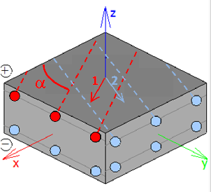
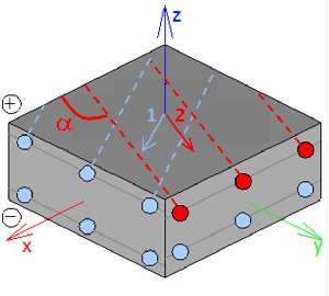
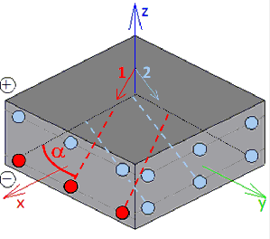
Note: Directions of designed reinforcement, in general independent for the upper and lower surface of the member, can be visualized by symbolic arrows (single arrow for each direction) using the option [Drawing directions for design] in View parameters setting. The arrows are drawn per member or individually for each mesh element, depending on the selected local coordination system of the member. If the LCS is the same for all mesh elements, then the arrows are drawn only once for the whole member near the centre of gravity. Moreover, when results related to specific reinforcement direction are presented, only the arrow associated with this direction and surface is automatically drawn. The visualization of the arrows can be modified by Colours/Lines settings to distinguish each direction specifically for better orientation in results.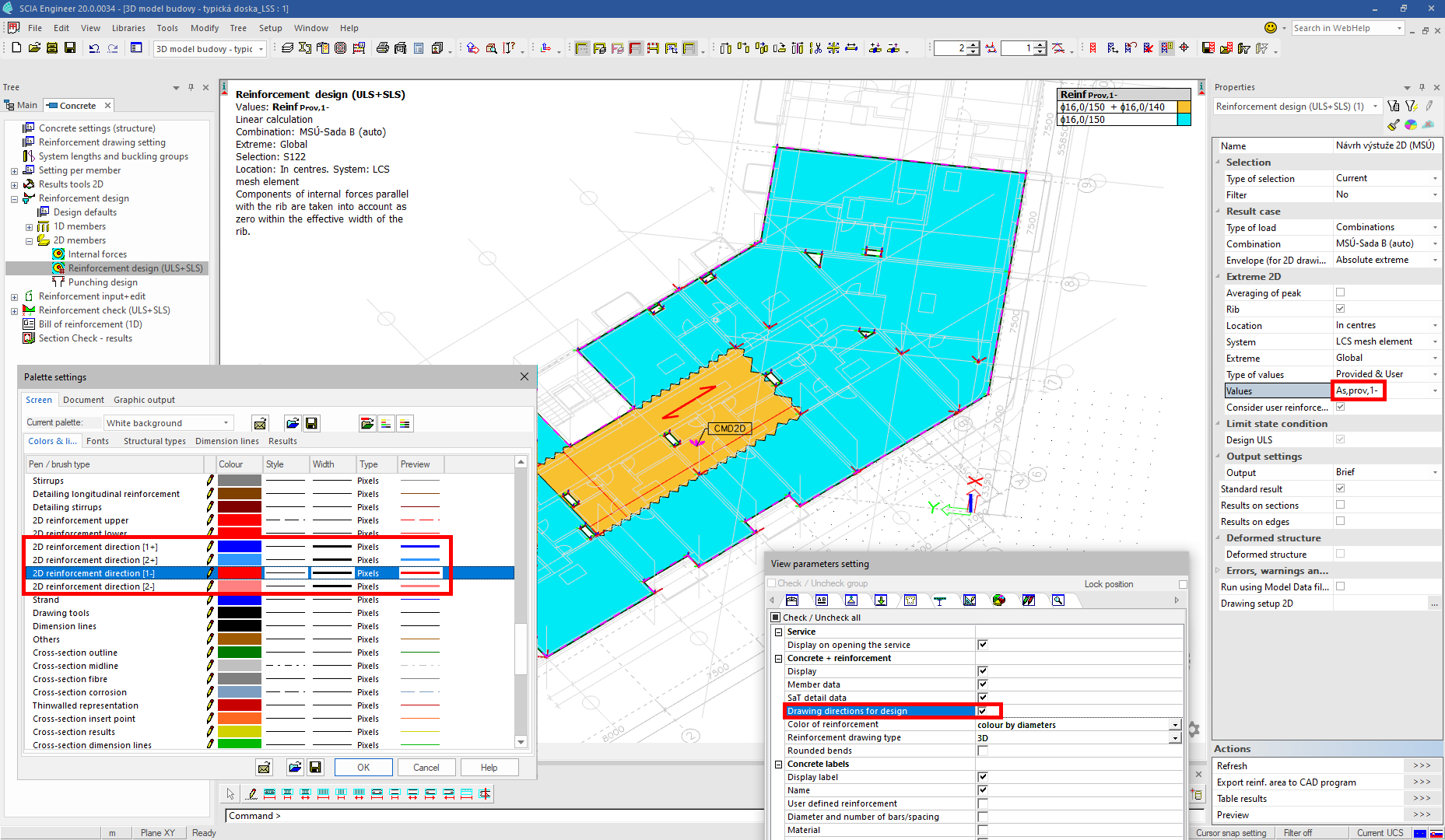
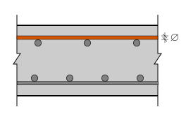
Shear
Diameter of shear reinforcement
| Description |
Definition of diameter of shear reinforcement (links) used in design of shear reinforcement |
| Default | Edit box; default = 8 mm |
|
Code |
- |
| Level | Standard |
|
Figure |
- |
| Member | Plate, Shell(Plate) |
Arrange perimeters of shear links by limits from detailing
| Description |
Setting if perimeters of shear links are calculated by limits from detailing or if they are defined by user |
| Default | Check box; default = True |
|
Code |
9.4.3 |
| Level | Standard |
|
Figure |
- |
| Member | Plate, Shell(Plate) |
The distance of the first perimeter from the column face
| Description |
The distance of the first perimeter from the column face |
| Default | Edit box; s0 = 100 mm; this item is visible only if check box above is set False |
|
Code |
9.4.3(4) |
| Level | Standard |
|
Figure |
- |
| Member | Plate, Shell(Plate) |
Radial spacing of perimeters
| Description |
Radial spacing of perimeters |
| Default | Edit box; sr = 150 mm; this item is visible only if check box above is set False |
|
Code |
9.4.3(1) |
| Level | Standard |
|
Figure |
- |
| Member | Plate, Shell(Plate) |
Wall, Shell (Wall), Deep beam
Longitudinal
Displaying of items in Design defaults for Wall, Shell (Wall) and Deep beam is dependent on setting Use a template of provided reinforcement, see above.
Use a template of provided reinforcement - True
When the provided reinforcement library is used then diameters for design are defined in design defaults directly.

Values of cover and angles are the same as in case of Use a provided reinforcement library is False. Diameters are linked via Provided reinforcement library. There are two links in fact for Wall and Deep beam.
Template of provided reinforcement (Wall)
| Description |
Link to provided library based for Wall |
| Default | Link to library; default is the first value from the library |
|
Code |
- |
| Level | Standard |
|
Figure |
- |
| Member | Wall, Shell(Wall) |
Template of provided reinforcement (Deep beam)
| Description |
Link to provided library based for Deep beam |
| Default | Link to library; default is the first value from the library |
|
Code |
- |
| Level | Standard |
|
Figure |
- |
| Member | Deep beam |
Use a template of provided reinforcement - False
When the provided reinforcement library is not used then diameters for design are defined in design defaults directly.
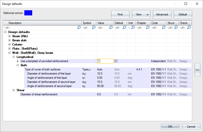
Then there is definition of items based for Both surface in one step. It means the same reinforcement is placed in each surface.
Both
Type of cover of both surfaces
| Description |
Selection of type of cover for first layer of reinforcement for both surfaces - Auto / User |
| Default | Combo box; Typec1 = Auto |
|
Code |
4.4.1 |
| Level | Standard |
|
Figure |
- |
| Member | Wall, Shell(Wall), Deep beam |
User cover of reinforcement layer
| Description |
User defined value of cover for first layer of reinforcement for both surfaces. |
| Default | Edit box; cuser1 = 30 mm; this item is visible only in case of Type of cover of both surfaces is User. |
|
Code |
4.4.1 |
| Level | Standard |
|
Figure |
- |
| Member | Wall, Shell(Wall), Deep beam |
Diameter of reinforcement of first layer
| Description |
Defined diameter of first reinforcement layer for both surfaces. |
| Default | Edit box; ds1 = 10 mm; this item is visible only if check box Use a template of provided reinforcement is set False. |
|
Code |
- |
| Level | Standard |
|
Figure |

|
| Member | Wall, Shell(Wall), Deep beam |
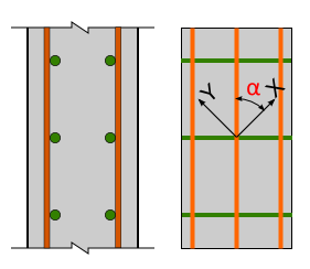
Angle of reinforcement of first layer
| Description |
Defined angle of first reinforcement layer for both surfaces |
| Default | Edit box; α1 = 0° |
|
Code |
- |
| Level | Standard |
|
Figure |
|
| Member | Wall, Shell(Wall), Deep beam |
Diameter of reinforcement of second layer
| Description |
Defined diameter of second reinforcement layer for both surfaces |
| Default | Edit box; ds2 = 10 mm; this item is visible only if check box Use a template of provided reinforcement is set False. |
|
Code |
- |
| Level | Standard |
|
Figure |

|
| Member | Wall, Shell(Wall), Deep beam |
Angle of reinforcement of second layer
| Description |
Defined angle of second reinforcement layer for both surfaces |
| Default | Edit box; α2 = 90° |
|
Code |
- |
| Level | Standard |
|
Figure |

|
| Member | Wall, Shell(Wall), Deep beam |
Shear
Diameter of shear reinforcement
| Description |
Definition of diameter of shear reinforcement (links) used in design of shear reinforcement in wall |
| Default | Edit box; default = 8 mm |
|
Code |
- |
| Level | Standard |
|
Figure |
- |
| Member | Wall, Shell(Wall), Deep beam |
Minimal concrete cover
Design working life
| Description |
Design working life is information used for determination of minimal concrete cover |
| Default | Edit box , default = 50 years |
|
Code |
4.4.1.2(5), table 4.3N |
| Level | Standard |
|
Figure |
- |
| Member | All |
Risk of corrosion attack
Corrosion induced by carbonation
| Description |
Exposure class caused by carbonation is used for determination of minimal concrete cover in Table 4.4N None - No corrosion induced by carbonation XC1 - Dry or permanently wet XC2 - Wet, rarely dry XC3 - Moderate humidity XC4 - Cyclic wet and dry |
| Default | Combo box; default = XC3 |
|
Code |
4.4.1.2(5), table 4.3N |
| Level | Standard |
|
Figure |
- |
| Member | All |
Corrosion induced by chlorides
| Description |
Exposure class caused by chlorides is used for determination of minimal concrete cover in Table 4.4N None - No corrosion induced by chlorides XD1 - Moderate humidity XD2 - Wet, rarely dry XD3 - Cyclic wet and dry |
| Default | Combo box; default = None |
|
Code |
4.4.1.2(5), table 4.3N |
| Level | Standard |
|
Figure |
- |
| Member | All |
Corrosion induced by chlorides from sea water
| Description |
Exposure class caused by chlorides from sea water is used for determination of minimal concrete cover in Table 4.4N None - No corrosion induced by chlorides from sea water XS1 - Exposed to airborne salt but not in direct contact with sea water XS2 - Permanently submerged XS3 - Tidal, splash and spray zones |
| Default | Combo box; default = None |
|
Code |
4.4.1.2(5), table 4.3N |
| Level | Standard |
|
Figure |
- |
| Member | All |
Free / thaw attack
| Description |
Additional Exposure class caused by freezing or thawing None - No Freeze/Thaw Attack XF1 - Moderate water saturation, without de-icing agent XF2 - Moderate water saturation, with de-icing agent XF3 - High water saturation, without de-icing agents XF4 - High water saturation with de-icing agents or sea water |
| Default | Combo box; default = None |
|
Code |
4.4.1.2(12) |
| Level | Standard |
|
Figure |
- |
| Member | All |
Chemical attack
| Description |
Additional Exposure class caused by chemical attack None - No chemical attack XA1 - Slightly aggressive chemical environment according to EN 206-1, Table 2 XA2 - Moderately aggressive chemical environment according to EN 206-1, Table 2 XA3 - Highly aggressive chemical environment according to EN 206-1, Table 2 |
| Default | Combo box; default = None |
|
Code |
4.4.1.2(12) |
| Level | Standard |
|
Figure |
- |
| Member | All |
Risk of abrasion attack
| Description |
Additional Exposure class caused by abrasion attack None - No abrasion XM1 - Moderate abrasion XM2 - Heavy abrasion XM3 - Extreme abrasion |
| Default | Combo box; default = None |
|
Code |
4.4.1.2(13) |
| Level | Advanced |
|
Figure |
- |
| Member | All |
Possibility of special control
Special geometric control
| Description |
To take into account additional deviation to nominal concrete cover caused by special geometric control |
| Default | Check box; default = False |
|
Code |
4.4.1.3(3) |
| Level | Advanced |
|
Figure |
- |
| Member | All |
Special concrete quality control
| Description |
To take into account additional deviation to nominal concrete cover caused by special concrete quality control |
| Default | Check box; default = False |
|
Code |
4.4.1.2(5) |
| Level | Advanced |
|
Figure |
- |
| Member | All |
Risk of casting on atypical surface
| Description |
To take into account additional deviation to nominal concrete cover caused by casting on atypical surface Standard - No additional deviation to nominal concrete cover Against prepared ground - Concrete cast against prepared ground Against soil - Concrete cast directly against soil Uneven surface - Increasing due uneven surface |
| Default | Combo box; default = Standard |
|
Code |
4.4.1.3(4) |
| Level | Advanced |
|
Figure |
- |
| Member | All |
Concrete characteristic
Type of concrete
| Description |
To take into account additional deviation to nominal concrete cover caused by production type In-situ - Concrete is cast directly on the construction site Prefabricated - Elements are precasted in factory |
| Default | Combo box; default = In-situ |
|
Code |
4.4.1.3(1P, 3) |
| Level | Standard |
|
Figure |
- |
| Member | All |