3 Design of the prestressing
For the design of prestressing force it is supposed that prestressing tendons are designed in scheme d) from the figure below. One half of the tendons in each direction is uniformly distributed in the span and one half is concentrated around the columns. This seems to be the optimum solution with respect to both design and economy.
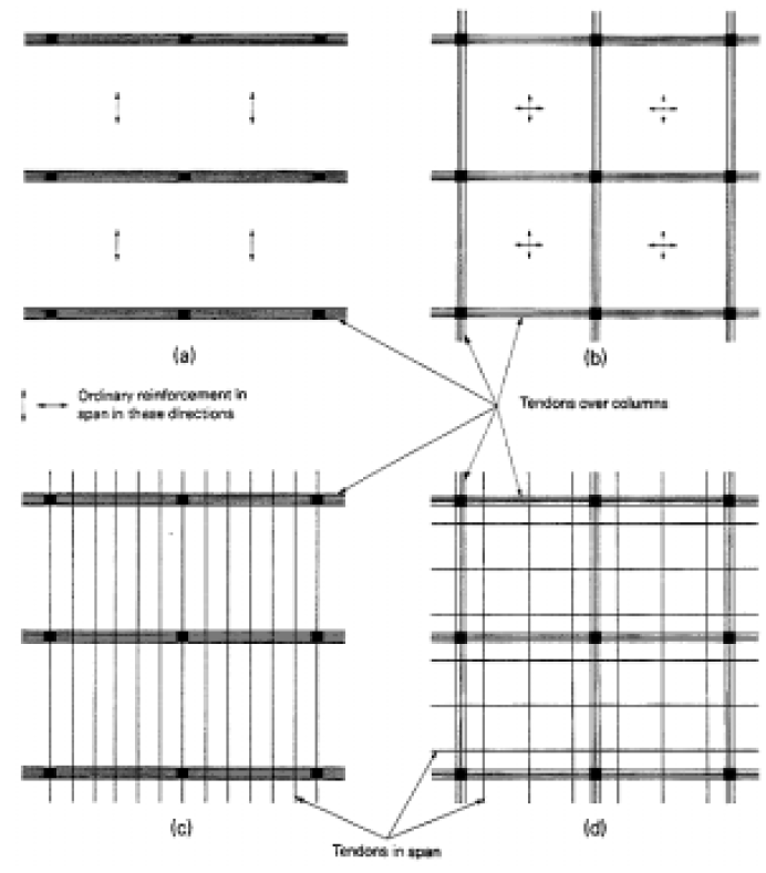
Fig. 7 Tendon layout (picture taken from http://www.vsl.net/Portals/0/vsl_techreports/PT_Slabs.pdf)
The actions of the tendons from the option d) on the slab are visible on the "Fig. 8 Actions of the tendon on the slab (picture taken from http://www.vsl.net/Portals/0/vsl_techreports/PT_Slabs.pdf)"
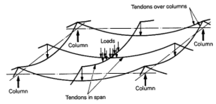
Fig. 8 Actions of the tendon on the slab (picture taken from http://www.vsl.net/Portals/0/vsl_techreports/PT_Slabs.pdf)
The recommendations for design are taken from http://www.vsl.net/Portals/0/vsl_techreports/PT_Slabs.pdf.
|
Maximum tendon spacing in the span |
6.0*h |
|
Inflection point of the tendons |
ds/2 from the column edge |
|
Minimum radius of curvature |
r = 2.50 m |
3.1 Design of prestressing force
The very simple load-balancing method is used for the design of prestressing. At the beginning it is necessary to estimate the losses of prestressing. The following losses are taken into account as a simplification:
|
Short term losses |
10% (only for model type Equivalent load) |
|
Long term losses |
15% |
3.1.1 Concrete cover
The following settings are required for this structure:
|
Exposure class |
XD1 |
|
Design working life |
50 years |
3.1.1.1 Concrete cover for prestressing
Nominal concrete cover ( ) has to be calculated

Structural class (Table 4.3N "EN 1992-1-1 Eurocode 2, Design of Concrete Structures – Part 1: General rules and rules for buildings, European Committee for Standardization, December 2004.")
|
Default |
4 |
|
Slab structure |
-1 |
|
Final structural class |
4 – 1 = S3 |
Minimal cover based on durability for S3+XD1 (Table 4.5N)

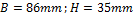
Minimal cover based on bond (4.4.1.2(3) "EN 1992-1-1 Eurocode 2, Design of Concrete Structures – Part 1: General rules and rules for buildings, European Committee for Standardization, December 2004."). We suppose the rectangular ducts similar as in the following figure
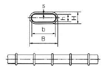
Fig. 9 Rectangular duct for post-tensioned slab

Calculation of minimal cover (formula 4.2 "EN 1992-1-1 Eurocode 2, Design of Concrete Structures – Part 1: General rules and rules for buildings, European Committee for Standardization, December 2004.")


Deviation of the concrete cover (4.4.1.3(1) "EN 1992-1-1 Eurocode 2, Design of Concrete Structures – Part 1: General rules and rules for buildings, European Committee for Standardization, December 2004.")

Automatic calculation of the concrete cover for prestressing reinforcement is not implemented in the version 2010.1
3.1.2 Maximal stress in strand
For the preliminary design the estimation of the short term and long term losses will be done. The short term losses are estimated as 10% and long term losses as 15%. It is necessary to calculate the maximal stress in strand after long term losses.
Maximal stress during tensioning (5.10.2.1(1) "EN 1992-1-1 Eurocode 2, Design of Concrete Structures – Part 1: General rules and rules for buildings, European Committee for Standardization, December 2004.")

Maximal stress after anchoring (5.10.3(2) "EN 1992-1-1 Eurocode 2, Design of Concrete Structures – Part 1: General rules and rules for buildings, European Committee for Standardization, December 2004.")

From the value above we can say the initial stress has to be lower than 1488 MPa. The initial stress was set to 1450 MPa.
The preliminary designed prestressing forces per one strand are:
- after short term losses (10%)

- after long term losses (15%)

For the determination of the amount of strands the force after long term losses  will be used.
3.1.3 Determination of prestressing force – load balancing method
Required prestressing force is determined using load-balancing method. This method was first published by the T.Y. Lin in 1963 "Lin T. Y, Load balancing method for design and analysis of prestressed concrete structures, ACI journal, June 1963". It is supposed that 80% of permanent and variable load is balanced by the prestressing force in this case. The surface load (f=g+q) from the span area is spread to the column line according to following figure. The triangular spreading is used for calculation of the load fx(y)1(2)*. This triangular load is substituted by the rectangular line load fx(y)1(2). The recalculated load is used for the load balancing method. As was written above that 50% of tendons will be designed in the column line and 50% in the span area.

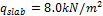
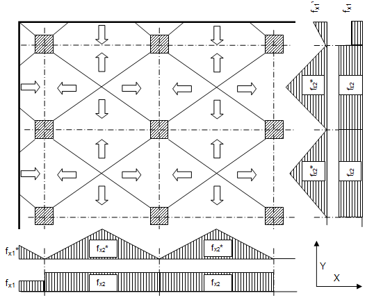
Fig. 10 Load distribution
Triangular line load
a) permanent load


b) variable load


Rectangular recalculated line load
a) permanent load


b) variable load


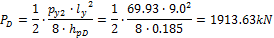
Using load-balancing method the rectangular recalculated line loads (80%(g+q)) are balanced by the uniform load representing the prestressing force.


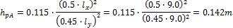
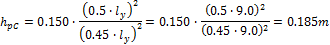
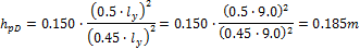
The design for each direction (x,y) has to be done with respect to the different camber (hp) of the parabolic tendon in each direction. These cambers are determined from the minimal radius of the tendon above the support and maximal possible tendon eccentricity witch respect to the concrete cover of the tendon in the span. The camber is measured from the inflexion point to the maximal eccentricity in the span. The eccentricity in the x direction is less than in the y direction because the tendons are crossing each others.
As the simplification the geometry of the tendon in the edge part of the slab is considered as straight line. It means the equivalent load px1 is not taken into account and effect of the prestressing is covered by the vertical point force Vx1.
Fig. 11 Section in the slab for design of prestressing
Direction x
- Section A – 50% of the tendons will be in the column line
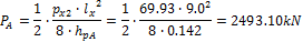
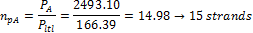
The 5 pieces of the 3strand tendons are used

- Section B – 50% of the tendons will be in the span
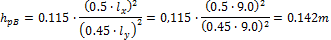
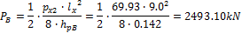
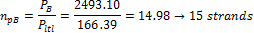
The 5 pieces of the 3strand tendons are used

Direction Y
- Section C – 50% of the tendons will be in the column line
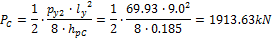
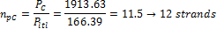
The 4 pieces of the 3 strand tendons are used

- Section D – 50% of the tendons will be in the span
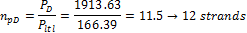
The 4 pieces of the 3 strand tendons are used
