Introduction
The analysis of foundation structures is challenged by the problem of modelling of the part of the foundation that is in contact with subsoil. The best solution is to use 2D model of the subsoil that properly represents the deformation properties of the whole under-foundation massif by means of surface model. The properties of such model are expressed by what is called interaction parameters marked C. These parameters are assigned directly to structure elements that are in contact with the subsoil and they influence the stiffness matrix.
To simplify the matter, we may imagine that C is the characteristics of elastic, more precisely pseudo-elastic, links, or surface spring constants that change according to the actual state of the analysed system. We may also use the professional slang that calls it "support on C parameters", which is the generalisation of standard Winkler idea of the supporting in the form of thick liquid g = C1 (MNm-3) or in the form of infinitely dense system of vertical springs. The generalisation is very important and deals mainly with the consideration of significant shear distribution in the subsoil that is neglected by Winkler model. The parameters of the interaction between the foundation and the subsoil depends on the distribution and loading level, or the contact stress between the structure surface and the surrounding subsoil, on the geometry of the footing surface and on mechanical properties of the soil.
Calculation module Soil-in takes account of all the mentioned dependencies.
As the C parameters influence the contact stress and vice versa – the distribution of the contact stress have impact on the settlement of the footing surface and thus the C parameters, it is necessary to use an iterative solution.
The influence of subsoil in the vicinity of the structure
The modelling of the interaction between a structure and subsoil requires that the influence of the subsoil outside of the structure be taken into account. This outside-subsoil supports the edges of the foundation slab due to shear stiffness. In the past, special procedures were recommended to model this phenomenon. The current versions of SCIA Engineer employ a sophisticated solution whose principle is described in the following paragraph.
The program automatically adds to the edge of the analysed foundation slab springs that approximately substitute the effect of what is termed support elements (1 to 2 metre wide strip located along the edges of the foundation slab, the thickness of this strip is almost zero). The solution obtained through this approach takes into account the effect of the subsoil outside (in the vicinity) of the analysed foundation slab.
In comparison with a solution without such springs, the results obtained with the springs gives smaller deformation of the foundation-slab edges which means larger bending moments in the foundation slab.
The springs oriented in the global z-direction are assigned to all edge nodes except the situation when a node already has another spring assigned or if a rotation of a node is specified. In that case, the program assumes that the user has already defined a special type of support and that it is not wanted to alter that special configuration automatically on the background.
These exceptions can be used to deliberately suppress the implementation of edge-springs along certain lines. The user can define very small line springs along required lines (edges) and thus eliminate the effect of the surrounding subsoil (e.g. if a sheet pile wall is installed).
Soil-in output
The results from the soil-in iteration are the C parameters C1z, C2x and C2y.
Parameters C1x and C1y are always defined by the user.
C1z - resistance of environment against wP (mm) [C1z in MN/m3]
C2x - resistance of environment against wP/xP (mm/m) [C2x in MN/m]
C2y - resistance of environment against wP/yP (mm/m) [C2y in MN/m]
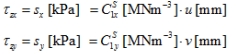
C1x - resistance of environment against uP (mm) [C1x in MN/m3]
C1y - resistance of environment against vP (mm) [C1y in MN/m3]
Usually, C2x is considered equal to C2y and C1x equal to C1y, because the calculation is done by so called isotropic variant of the calculation of C2 parameter.
The soil-in calculation is available when the specific functionality is active.
Check Subsoil on the left part and the Soil interaction on the right part of the functionality tab:
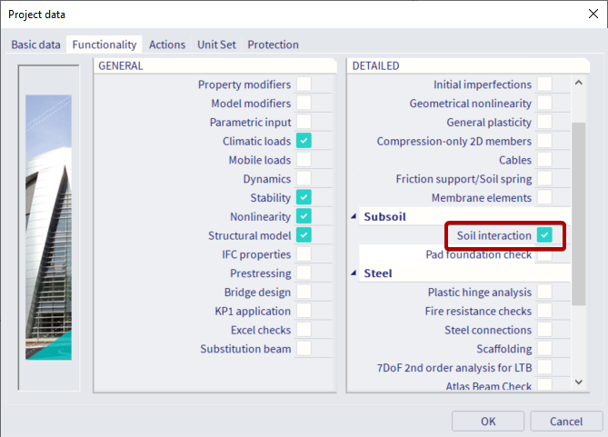
The Soil interaction is available only for Plate XY and General XYZ type of project.
C parameters (explanation from theoretical background of FEM solver)
C1 - Parameters of the interaction of the foundation with the surface 2D model of the subsoil in physical relation containing components of displacement u, v, w.
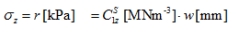
Winkler formula for vertical components:
Winkler formula for horizontal shear components:
C2- Parameters of interaction of the foundation with the surface 2D model of the subsoil in physical relations containing the first derivative of settlement.
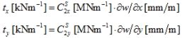
Paternal formula for shear forces:
C1z - foundation compression modulus of the Winkler type, expressing resistance to the vertical displacement of the subsoil surface.
C2x, C2y,C2xy - foundation shear modulus expressing resistance to the shear components in the x and y direction of the subsoil surface, generally different in positive and negative shears gxy, gyz(dilatancy and contractancy effects).
Pasternak Gp modulus is our C2.
Pasternak differential equation:
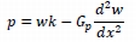
p - pressure
k - modulus of sub-grade reaction
Gp - shear modulus of the shear layer and it is related to rotation in the differential equation.
Rotation of the surface = bevel dw/dx (see the picture)
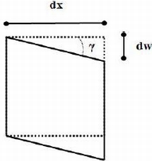
w - displacement
g - shear strain