Advanced tips
Foundation at great depth
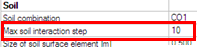
For better convergence of soilin iterations for foundation at great depth user can set at solver setup in group Soilin - Thickness of loose layer at contact level [m]. The recommended value is 0,500 m. More info in Required parameters for Soil-in calculation.
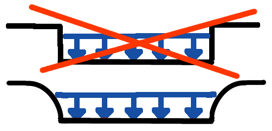
The effect of the subsoil outside the structure
The nearest subsoil around the loaded structure is also affected by its settlement. The better realistic picture how it works in the reality is displayed below.
Calculation of the nearest surrounding of the structure is a specific use case. It is recommended to add one more plate to the structure for this purpose – additional subsoil element.
The new plate should be inserted with the minimum thickness (e.g. 0,01mm) and placed next to the foundation.
The C parameters for this affected subsoil around the structure are calculated this way also.
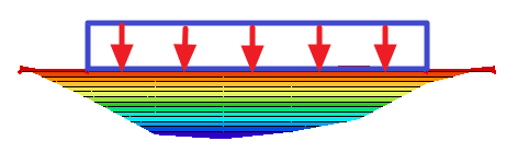
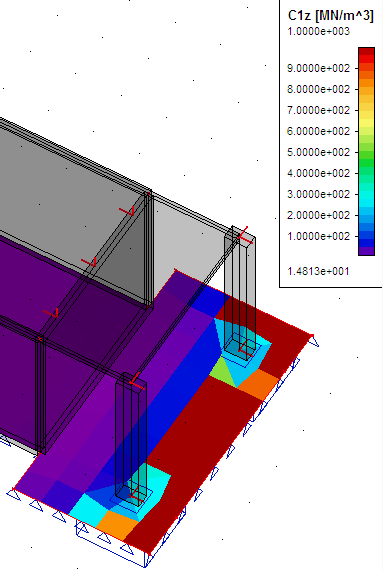
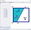
The deformed subsoil calculated by the SCIA Engineer:
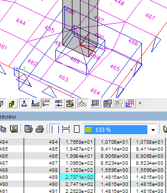
Calculated C parameters:
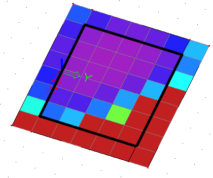
The structure is marked by the black rectangle and around this is one more plate - surrounding plate – with thickness 0,001mm.
Automatic calculation of the edge supports
When user don’t use any subsoil elements then the program will eliminate the neglect of the subsoil on edges by an automatic inserting of vertical supports on the foundation edges.
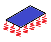
The calculation of those supports is based on already known C parameters. The program try to support the plate in the same way as it should be supported by the subsoil itself. This leads to approximate model where the sum of reaction is contact stress with reactions in those nodes.
This solution can be sometimes undesirable – e.g. if there is a second foundation near by the calculated one or there is some other support under or near the foundation edge.
This automatic input can be avoided manually. User can insert a spring with a small stiffness on the plate edges and then the system won’t use automatic input of vertical supports. This could be the additional subsoil elements.
Pad foundation and soil-in
The pad foundation is not connected with the soil-in calculation.
How to use soil-in for the pad foundation check:
- Create additional structure to calculate the C parameters in the nearest surrounding (it is described in the previous tip)
Calculated C parameters on the surrounding plate –> C parameters for the pad foundation
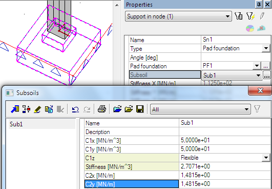
- Calculated C parameters can be used in the Subsoil library. Put the values from the table to the Subsoil library.
- Run the linear calculation again.
- Check the pad foundation in a standard way.
What if the model is correct but the iteration is not finished
Sometimes the model is correct but some circumstances may cause unfinished iterative process. The results in cycles don’t lead to one set of C parameters but on the contrary, the results are more and more different.
This can be caused by some tensions in the foundation plate, specific foundation members and similar problems.
How to solve those problems:
- It is necessary to check the model. It must be correct – the mesh elements are not triangular, the element´s Z axis is upward, the foundation plate must be under the soil surface and so on.
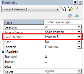
- Check the iteration cycles in results – contact stresses, type of loads – soilin iteration.
First few iteration cycles will be probably quite OK and after some time the results become messy.
Find one cycle (between those correct ones) where the results seem to be close to the reality – e.g. 5thcycle. Use this value in the solver setup for number of iteration cycles.
- Start the linear calculation again, it will be finished after the 5th iteration cycle with results most closest to the reality.
The correct cycle is between 2nd and 5th cycle in the most cases.
What if the load is wrongly inserted?
When the plate is not in compression, then soilin cannot be calculated properly.
There could be a message about wrong total resultant:
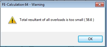
This may happen when loads are from the bottom to the top, or when there is some change in local LCS of the plate.
What if the symmetrical structure gives non-symmetrical results?
This may happen when additional subsoil elements are not added around the structure.
Also when the soilin didn’t find the correct result and calculation is stopped too soon. (For example when solver setup defines only few soilin cycles.)
What if geological fault in the subsoil is needed?
The main subsoil surface is created automatically when a structure and a borehole is inserted to the project. The size of the subsoil outline is calculated from the structure size, positions of boreholes and some offset around.
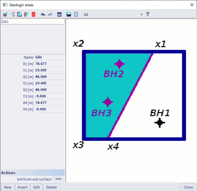
The geological fault is created when the second area is inserted to the main one.
- Create structure and insert boreholes.
- The main subsoil surface is created.
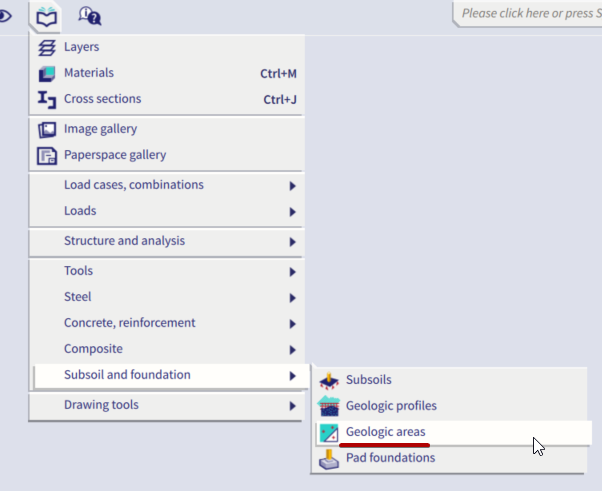
- Go to Libraries / Subsoil, Foundation / Geological areas, create a new area by its coordinates.

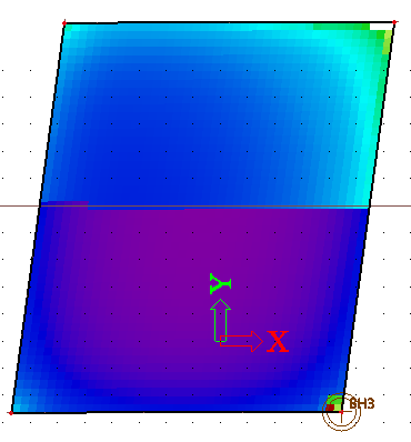
- Run standard Soilin calculation.
- Check results where geological fault is visible as a border between two gradients.