Initial Global Geometrical Imperfections
Definition, application
Since SCIA version 22.1., the global imperfections are treated as a standalone entity, which has its own library and items from this library (global imperfections) might be assigned to nonlinear combinations.
Global imperfection is one of the option how to define initial geometrical imperfection.
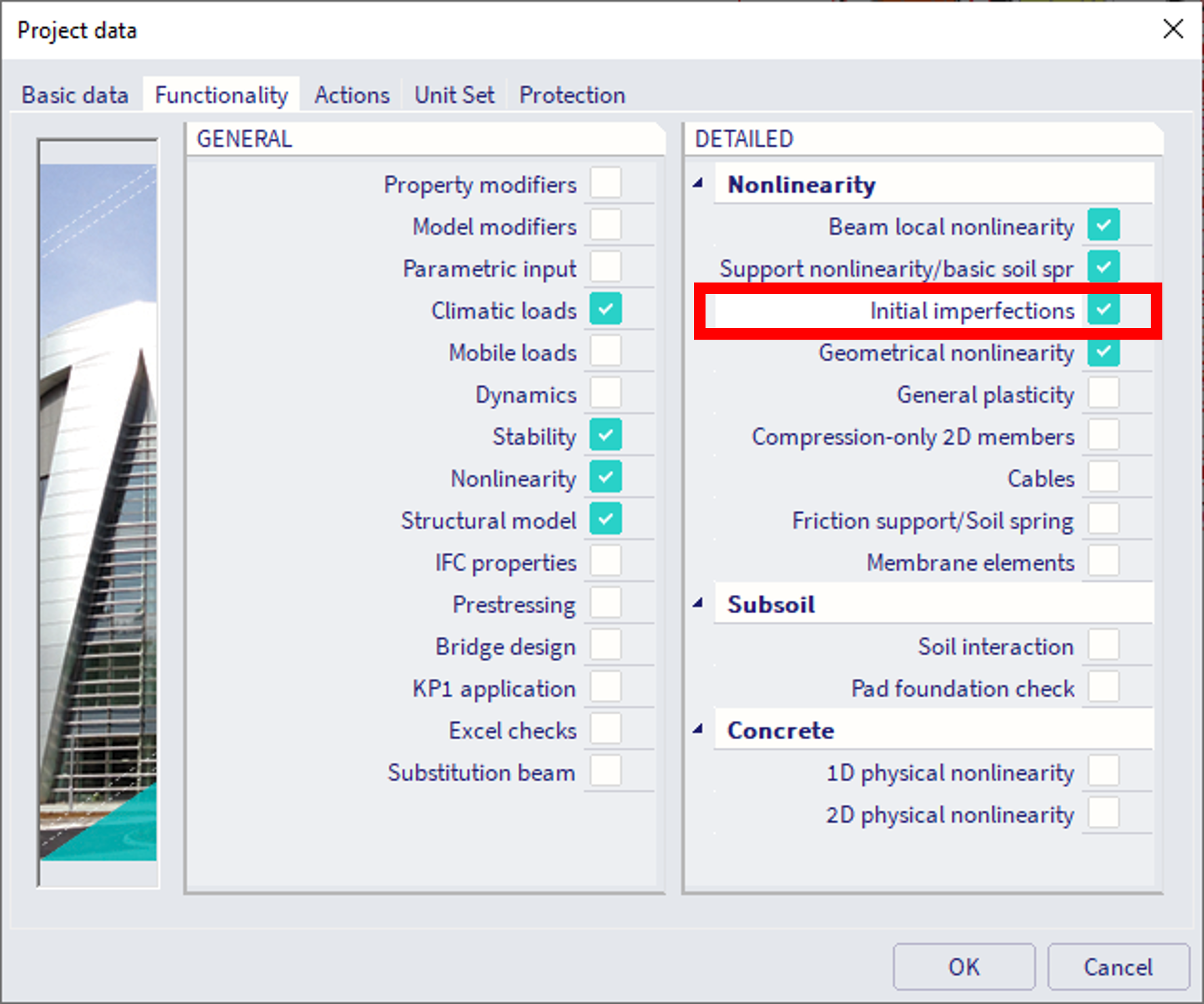
In order to define Global imperfections, in project data, functionality "Initial imperfections" needs to be selected:
Where to find in SCIA Engineer
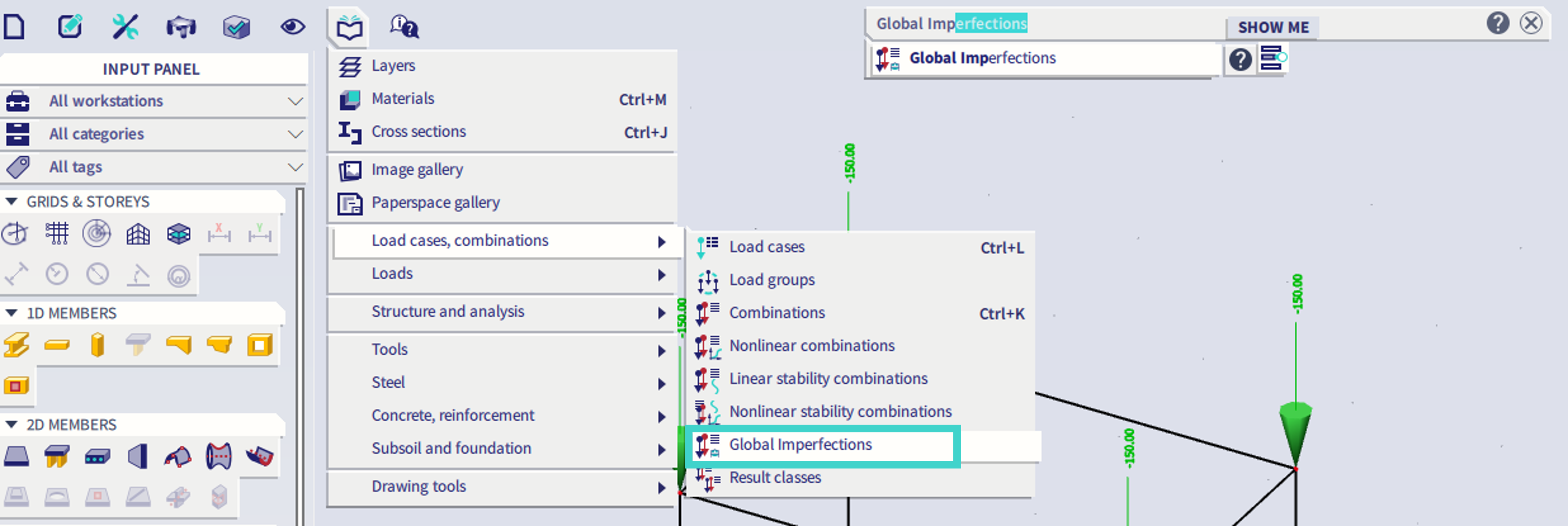
The Global Imperfections are to be found in: Libraries - Load cases, Combinations - Global imperfections.
How to create a new one
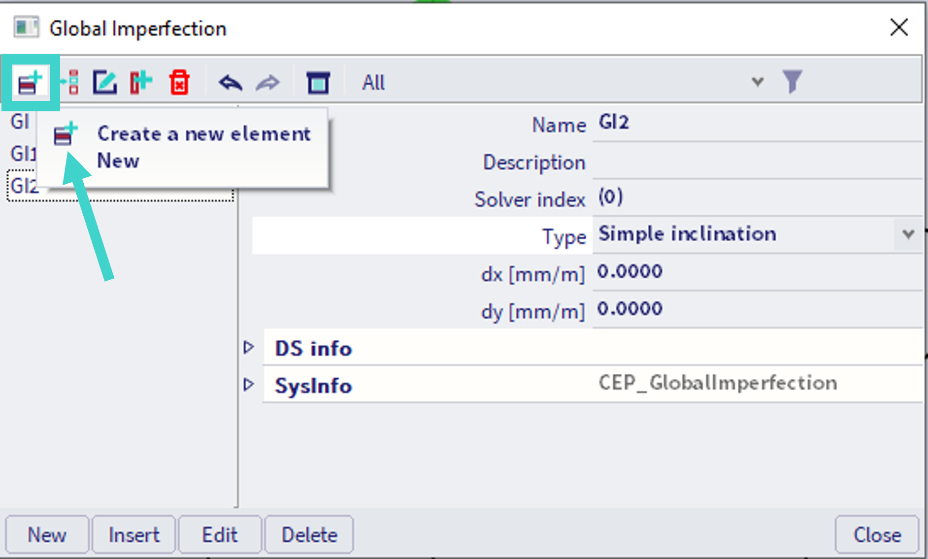
It is possible to create several entities within the library of Global imperfection. Default name of the created entities starts with "GI" and the number follows. Four various types might be defined, as discussed in the chapter below.
Types of Global Imperfections
| Imperfections | Specification | Description |
| Global imperfection | "Simple inclination" |
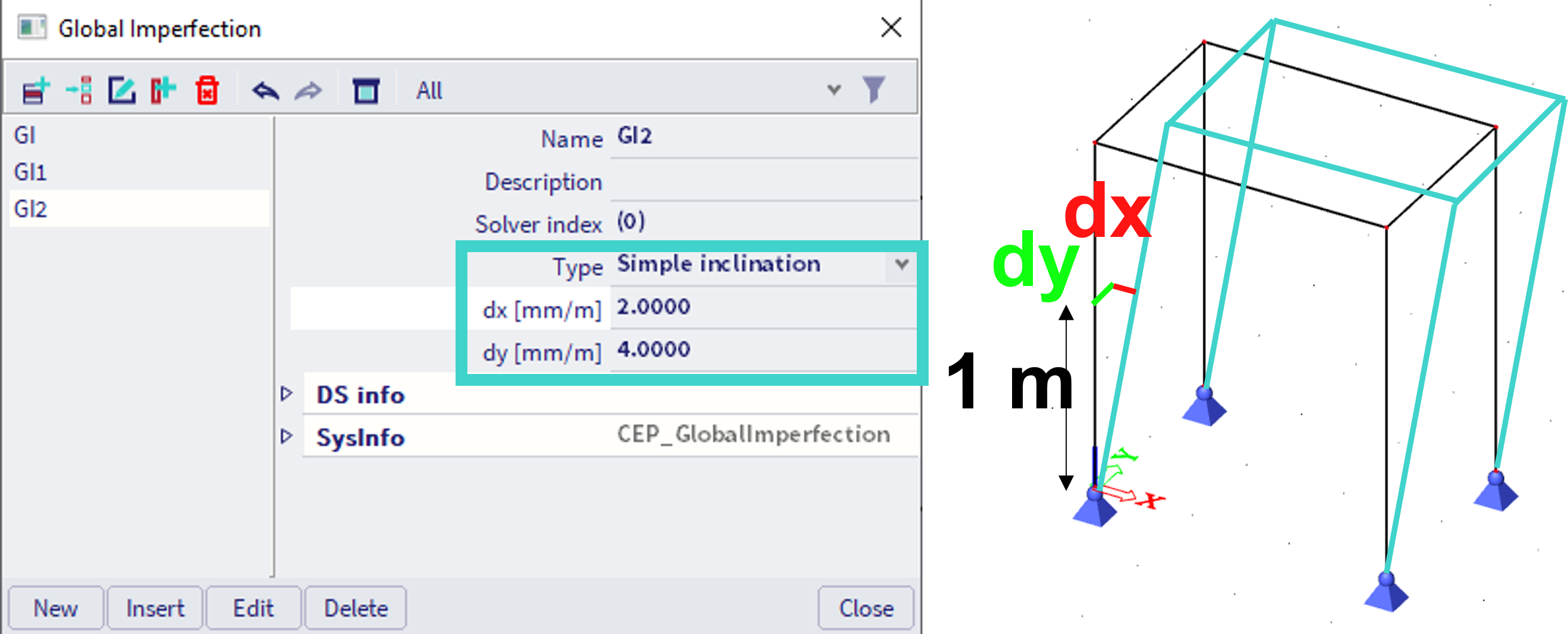
The imperfection is expressed in the form of a simple inclination. The inclination may be defined in millimetres per a metre of height of the structure. It means that only horizontal inclination in the global X and Y direction may be specified. The inclination is linearly proportion to the height of the building. This option is applicable mainly for high-rise buildings. It has no or minimal influence on horizontal structures. |
| "Inclination functions" | The initial imperfection is defined by a function (or curve). The user inputs the curve by means of height-to-imperfection diagram. This option is applicable mainly for high-rise buildings. It has no or minimal influence on horizontal structures. | |
| "Deformation from load case" | This option requires two-step calculation. First, a calculation for a required load case must be performed. The deformation due to this load case is then used as the initial imperfection for further calculation. | |
| Buckling shape |
This option requires two-step calculation. First, a stability calculation must be performed. The calculated buckling shape is then used as the initial imperfection for further calculation. Regardless of the approach, the initial imperfection can be defined for a non-linear combination only. It is one of the parameters that the user may define in the Non-linear combination manager. |
The calculated and displayed deformation is ALWAYS measured from the imperfect model, i.e. it does not represent the total deformation from the ideal shape, but the overall deformation from the imperfect shape.
Calculations taking account of any type of imperfection are non-linear calculations and as that they are sensitive to the size of finite elements. Or to be precise, they are sensitive to the number of finite elements per a member. The user MUST remember that a division giving just one finite element per a beam is NOT sufficient and may give completely misleading results.
Simple inclination
|
dx |
The inclination per one meter of height in the direction of global X-axis |
|
dy |
The inclination per one meter of height in the direction of global Y-axis |
Older description of this feature is also here.
Inclination functions
Since version 22.1., there is a simplification in the input of the inclination functions.
It is possible to define global initial imperfection as a combination of two functions, but each of these functions must have the same global direction as function domain.
An example is provided below. The Direction in order to define function domains is selected as Z (global coordinate system) - #A. It is possible to define imperfections in x and y axes directions, dx and dy respectivelly, both dependent on the global Z axis - dx(Z) and dy(Z). It is not possible to define dz(Z) - the corresponding property of "Function" has value of "none" and is greyed-out. In case the global direction for function domain is changed from Z to X, dx will be greyed out with no function assigned, and dy(X) and dz(X) might be defined. For global direction Y analogically. Each function might be multiplied by a scalar value (Factor) - in example below, for dx there is -1.5. Default value of the "Factor" is +1.0.
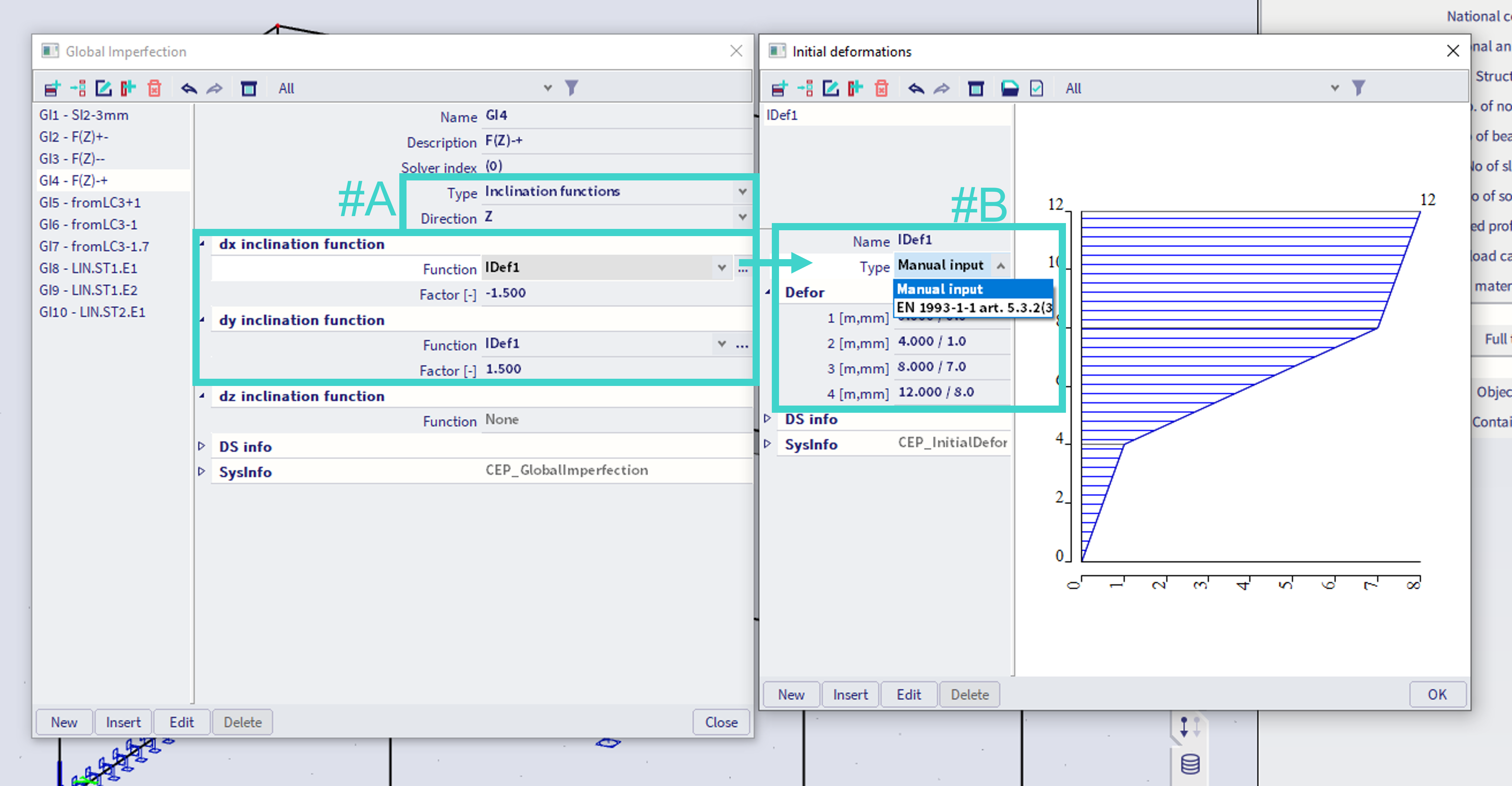
Each of these two "Function" properties might have an unique function assigned. The functions needs to be defined within the "Initial deformations" library, which might be found in the menu, or when the "..." button is clicked next to the "Function" in "Global imperfection" library. For each function, two options are available (#B):
1) Manual input - enables manual definition of the imperfection. In this case, user needs to define a function. Any possible coordinates of nodes outside the defined domain of this function are not extrapolated, but the edge values are considered (#C)- e.g. in the example below, which is a function of dx(Z), for Z coordinates below 0, dx = 0 mm is considered. For nodes above global Z coordinate of 12 m, dx = 8 * (-1.5) mm is considered (the value is multiplied by the factor from previous figure).
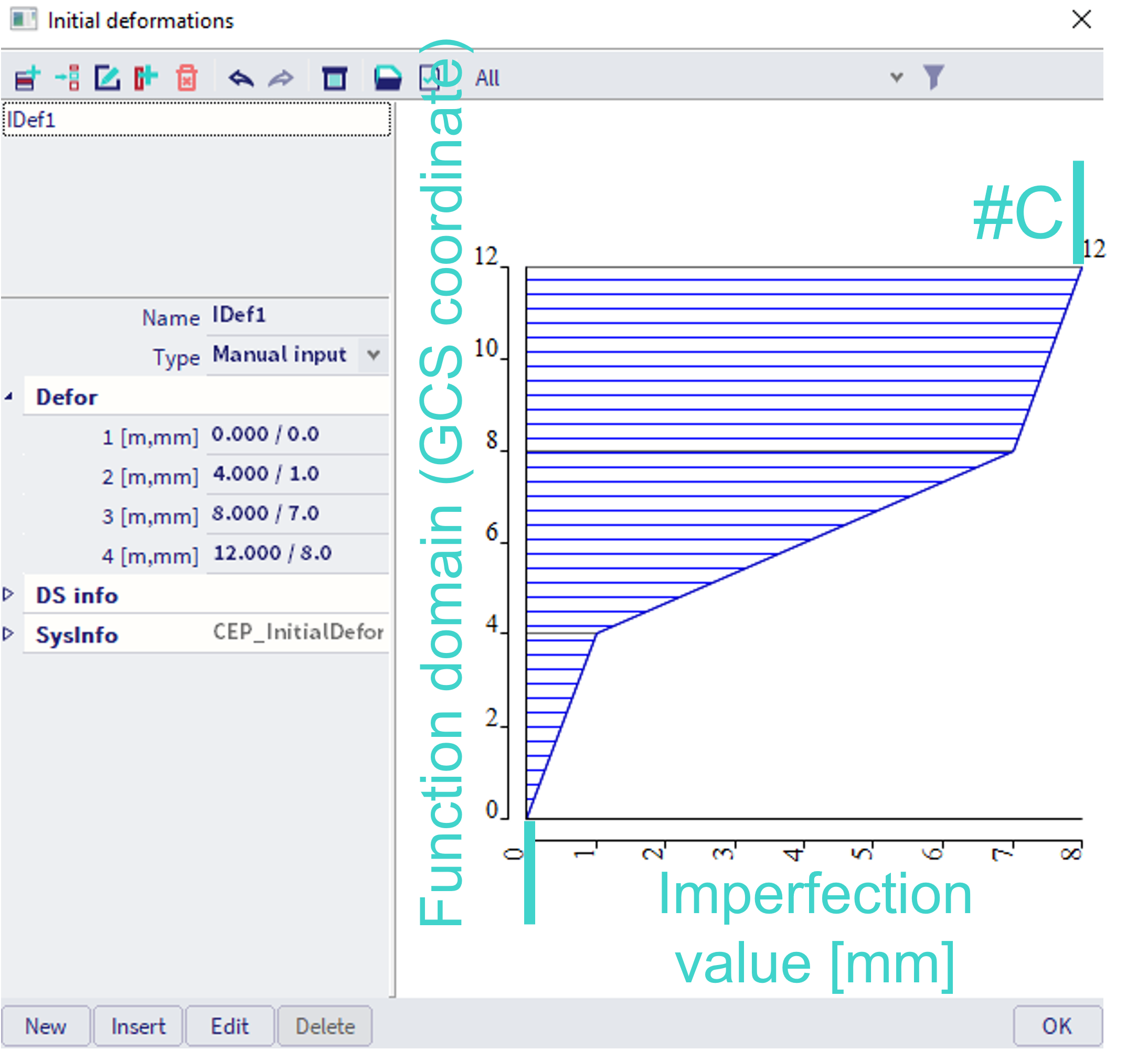
Note The function domain is on y-axis, as in most cases it is assumed the domain of the function will be the global Z coordinate, the height of the structure, and dx and dy will be defined.
2) Input based on the corresponding Eurocode - in example above 1993-1-1 - in this case, sway (as a angle) is defined based on corresponding Eurocode (depends on selected material in the project)
Older description of this feature is also here.
Deformation from load case
|
Load case |
The results obtained for the specified load case are imposed as the initial imperfection for further calculations. It means that the results for the specified load case must be calculated first. Only then the further calculations may be performed. |
Note: The results for the given load case (from linear analysis) are automatically calculated before nonlinear combination also if the linear analysis is not explicitly selected by the user.
See the theoretical background chapter for more details about the calculation of imperfections in the nonlinear analysis.
Older description of this feature is also here.
Buckling shape
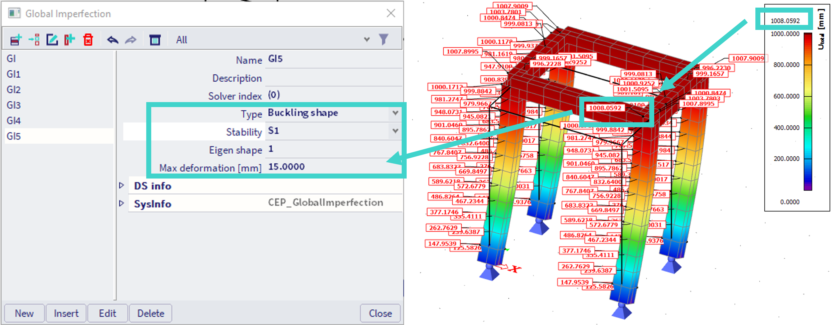
Based on selected stability combination and Eigen shape of this combination (in example above S1 and the 1st Eigenshape), the initial geometrical imperfection will be defined. Maximal deformation (in provided example 15 mm) will be considered in the point of the maximal normalized result from the linear stability analysis (in example above circa 1008 mm).