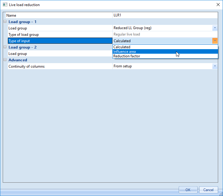
| Load group |
The load group for which the Type of input setting and its input (i.e. Reduction factor or Influence area) are applied. All load groups which have Apply live load reduction activated (in load group manager) are available for selection. |
| Type of load group |
A read-only field which displays the type of the load group selected in the previous input field. This is directly connected to the Occupancy type which can be specified in the load group manager for this load group. |
| Type of input |
The type of input to be specified can be set. The options depend on the type of load group that is selected. Options include Calculated (all reduced live load group types), Influence area (Regular live load groups only), Tributary area (Roof live load groups only) and Reduction factor (all reduced live load group types). When set to Calculated, the influence area and resulting reduction factor are calculated automatically. When set to Influence area or Tributary area, a value for the influence area or tributary area, respectively, can be input in the following field and the reduction factor calculated from this value. When set to Reduction factor, a value for the reduction factor can be directly input in the following field.
- Influence area: An input value for the member’s influence area. This value will be used instead of having the program automatically determine the influence area and will be used to calculate the reduction factor for regular live loads.
- Tributary area: An input value for the member’s tributary area. This value will be used instead of having the program automatically determine the tributary area and will be used to calculate the reduction factor for roof live loads.
- Reduction factor: An input value for the reduction factor which is to be used for the member. This value will be used directly rather than having a reduction factor calculated from the member’s influence area.
|
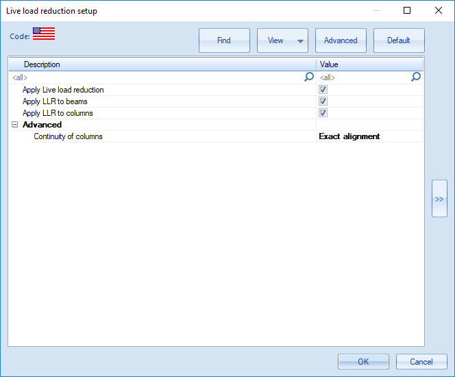
| Continuity of columns |
This setting defines the continuity of columns. It can be used to specify whether columns are intended to support only one floor or multiple floors.
If the column supports a single floor, only the influence area on the floor supported by the column under consideration is included in the calculation of the reduction factor. If a column supports multiple floors, the influence areas on all of the floors supported by the column under consideration are included in the calculation of the reduction factor. Setting this value in Live Load Reduction Member Data will override the value from the setup.
- None: Columns have no continuity and only the influence area on the floor supported by the column under consideration is included in the calculation of the reduction factor.
- Exact alignment: Columns have continuity and support multiple floors. In this case, columns can only be continuous with other columns which are directly in-line with and connected to the top of the column. This includes columns directly above and directly connected to the column under consideration as well as subsequent connected columns. The influence areas on all of the floors supported by the column under consideration are included in the calculation of the reduction factor.
- Approximate alignment: Columns have continuity and support multiple floors. In this case, columns can be continuous with any column within a defined area. The defined area is calculated by multiplying the ‘Continuity tolerance factor’ (below) by the tributary area of the column. The influence areas on all of the floors supported by the column under consideration are included in the calculation of the reduction factor.
|
| Continuity tolerance factor |
A value which is multiplied by the tributary area to define the area used to determine which columns are considered connected to a column. This value is only used when ‘Continuity of columns’ is set to ‘Approximate alignment’. |