Actions tab
The procedure for setting the parameters is the same as for other project parameters.
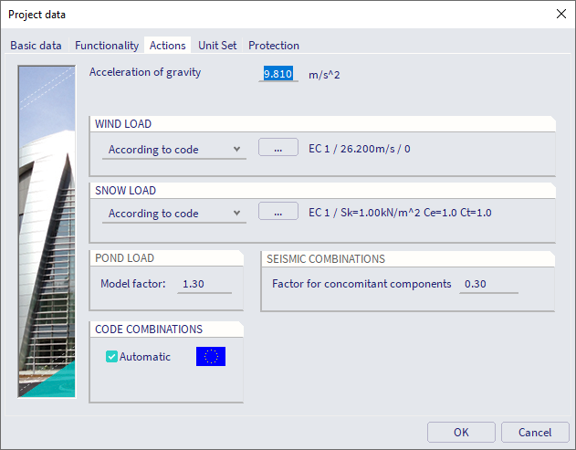
Acceleration of gravity
This parameter defines the acceleration of gravity g. By default g = 9.81 m/s2.
It is used in the following contexts (non exhaustive list):
- calculation of self-weight of materials based on their mass density (e.g. concrete density = 2'500 kg/m3 > self-weight = 24.525 kN/m3)
- calculation of seismic acceleration in some response spectrum generators (e.g. IBC)
Wind region
This parameter defines the region where the modelled structure will be located. The region may influence wind loads that the building will be exposed to. The user may choose from three options for this item:
|
None |
There is no wind load applied. |
|
According to code |
The wind region is defined according to appropriate national standard. |
|
User defined |
The user specifies the height-wind pressure curve. The real load is then defined as a force load but its type must be set to Wind. The load value input by the user then represents the load width. |
| User defined - more curves |
The user specifies more height-wind pressure curves. The real load is then defined as a force load but its type must be set to Wind. The load value input by the user then represents the load width. Each input load has defined a wind pressure curve in its properties. |
Wind setup for IBC
If the option According to code is set for IBC code a Wind setup dialog is shown.
|
Provisions |
Defines if formulas and values are used from provisions ASCE7-05 or provisions ASCE7-10. |
|
Importance factor/Risk category |
Defines Importance factor category, value and hurricane regions for ASCE7-05 or Risk category and hurricane regions for ASCE7-10. |
|
Directionality factor |
Defines Directionality factor according to code for selected structure type. |
| Gust effect factor |
Defines Gust effect factor according to code for selected structure type. |
| Basic wind | Defines a basic wind value. |
| Exposure and Topographic factor | Defines Exposure and Topographic factor according to code. |
| Calculation method | Defines a calculation method - All-heights/Low-rise for ASCE7-05 or Directional/Envelope for ASCE7-10. |
| Enclosure class | Defines if building is enclosed, partly enclosed or open. |
Library of wind pressures
When the option User defined is selected, it is possible to open [using the three-dot button] the Wind pressure database manager. In this manager the user may input the required wind curves.
Editing dialogue for the input of wind pressure
The Editing dialogue for the input of wind pressure can be opened from the Wind pressure database manager.
This dialogue contains the following controls.
Note: The defined wind curves can be reviewed and edited also through tree menu function Library >Loads > Wind pressures. This function becomes accessible only if parameter Wind region in the project setup has been set to Library.
Note: For more information about the generation of wind load see chapter Loads > Load generators > Wind generator.
Snow region
This parameter defines the region where the modelled structure will be located. The region may influence snow loads that the building will be subject to. The user may choose from three options for this item:
|
None |
There is be no snow load applied. |
|
According to code |
The snow region is defined according to appropriate national standard. |
|
Snow weight |
The user specifies the snow weight per square meter. The real load is then defined as a force load but its type must be set to Snow. The load value input by the user then represents the load width. |
Note: For more information about the generation of wind load see chapter Loads > Load generators > Snow generator.
Pond load
The Model factor concerns a reduction factor which is used during the calculation of Pond loads.
More specifically, during the deflection calculation of the water accumulation, the stiffness of the structure is divided by this factor.
Note: More information about Pond loads is given in the chapter Loads > Load generators > Pond water.
Seismic combinations
For codes that support seismic load case combinations with concomitant direction components (e.g. Eurocode), the parameter Factor for concomitant components defines the coefficient applied to concomitant direction seismic load cases in a seismic envelope. Typically, with 2 seismic load cases EQX and EQY and Factor for concomitant components = 0.30 (default), the seismic envelope will contain the following combinations:
- +/- 1.00 * EQX +/- 0.30 * EQY
- +/- 0.30 * EQX +/- 1.00 * EQY
Note: More information about seismic combinations is given in the chapter Seismic combinations - Eurocode.
Code combinations
This tab provides for the adjustment of load case parameters for automatic generation of load case combinations based on a particular national standard.